How the DWC 2440 CNC Keeps Jeff Clary Carving
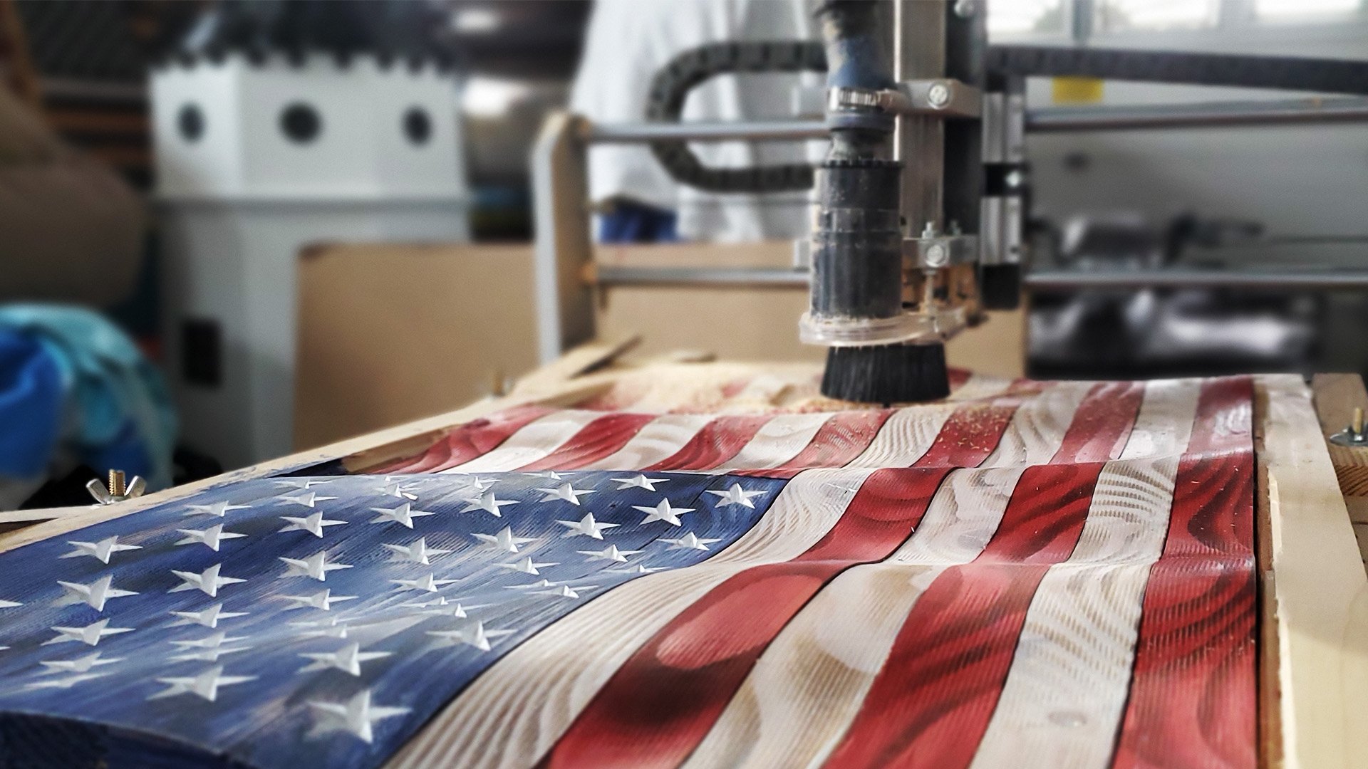
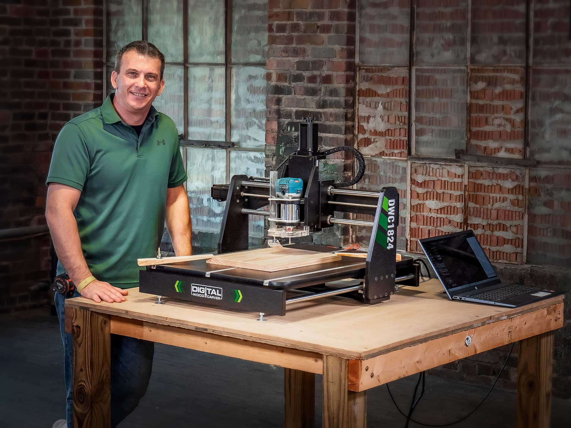
For many CNC owners, the journey starts with a business goal, custom signs, furniture, or detailed carvings that bring in extra income. But for Jeff Clary, his DWC 2440 CNC has become more than just a tool for making money. It’s now his passion.
A CNC That Pays for Itself
Jeff purchased his DWC 2440 in 2017, and over the years, it proved to be a profitable investment. Like many Digital Wood Carver owners, he used it to create and sell custom wood carvings, turning his hobby into a business. The precision and reliability of the machine made it easy to produce quality work that customers loved.
Retirement Brings a New Purpose
Now retired, Jeff has shifted his focus from selling to creating for himself.
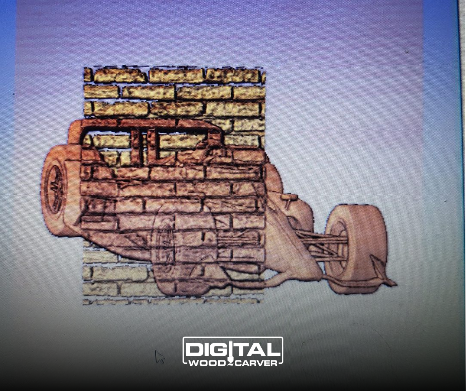
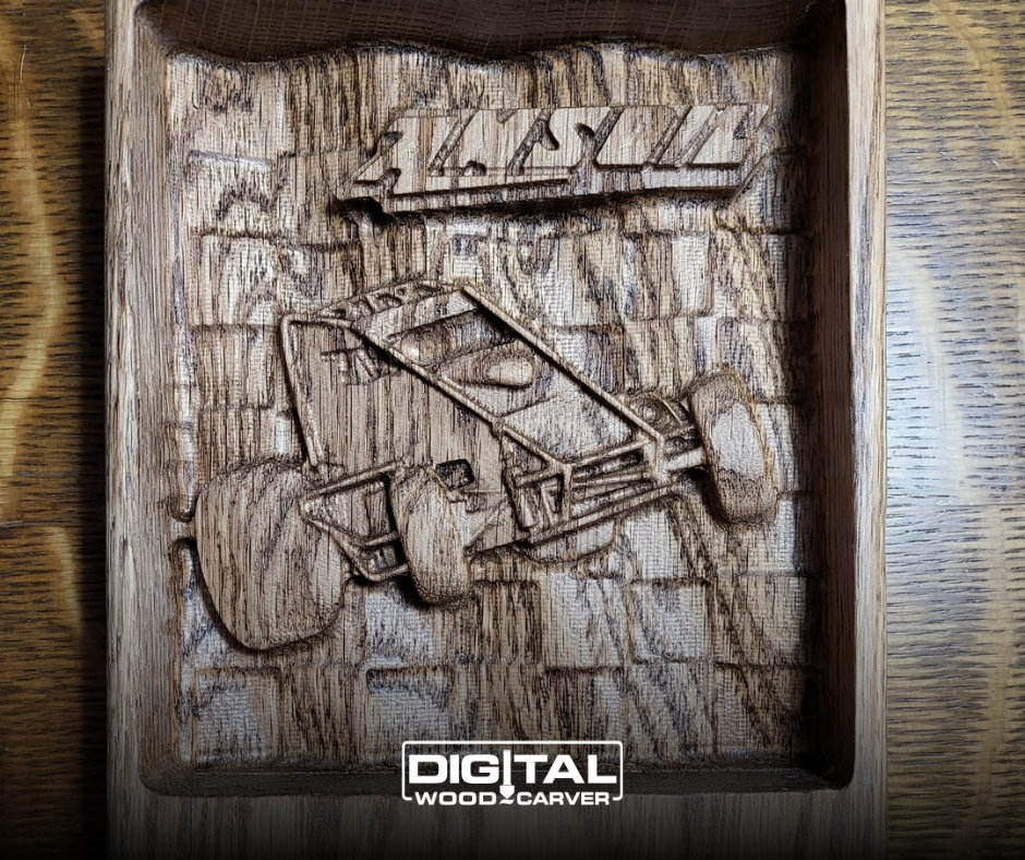
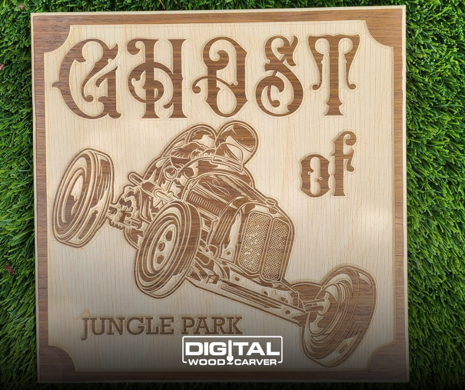
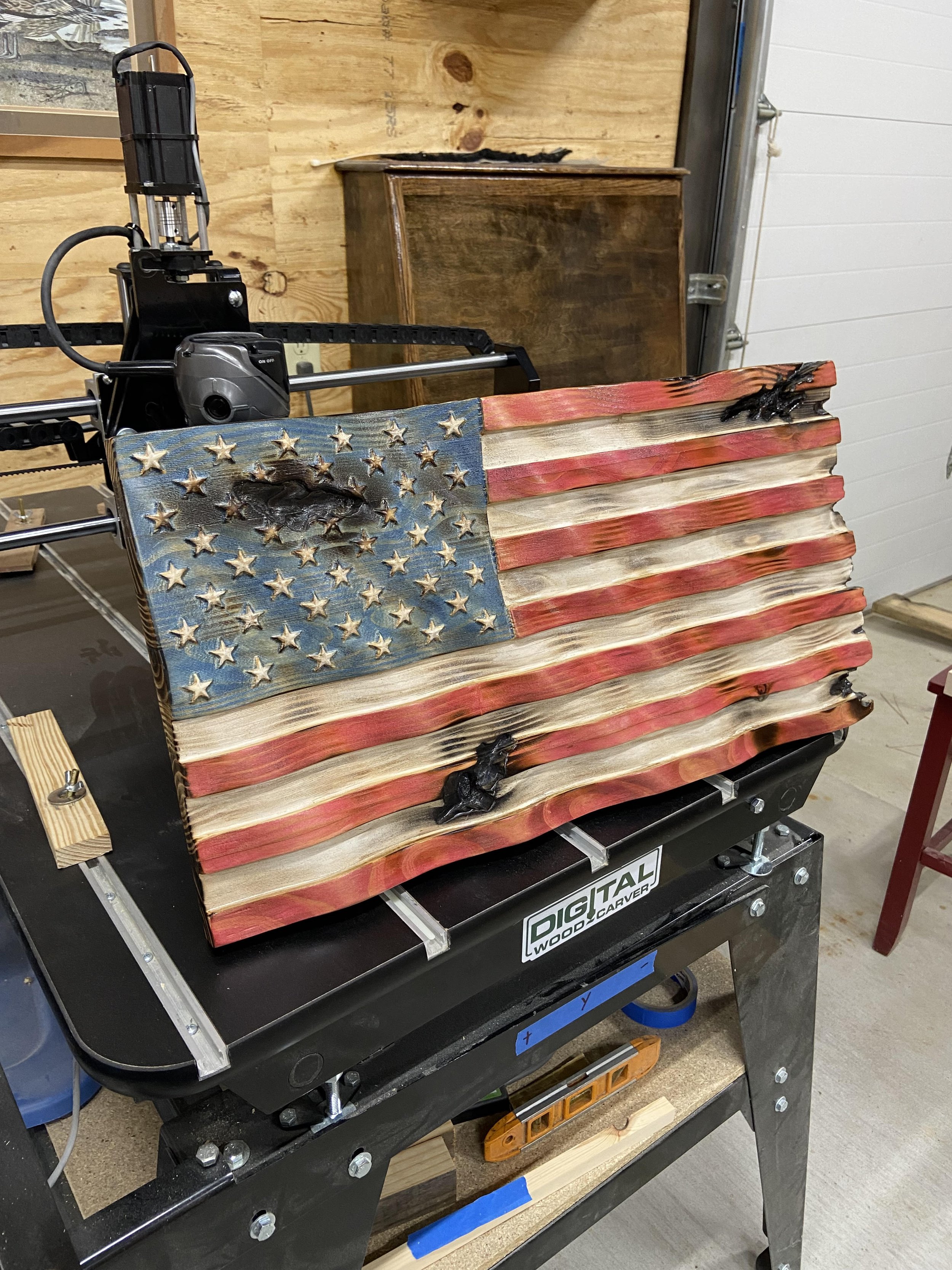
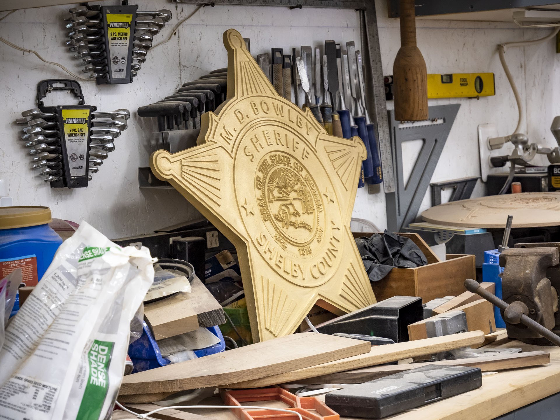
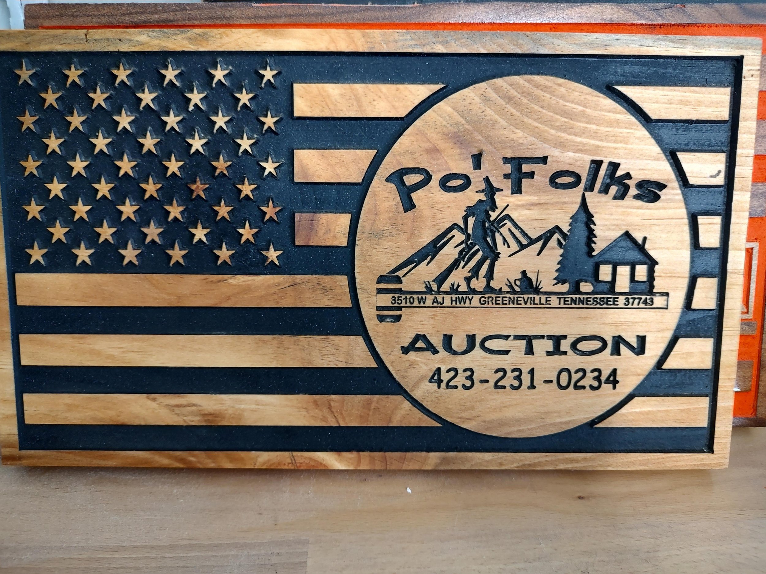
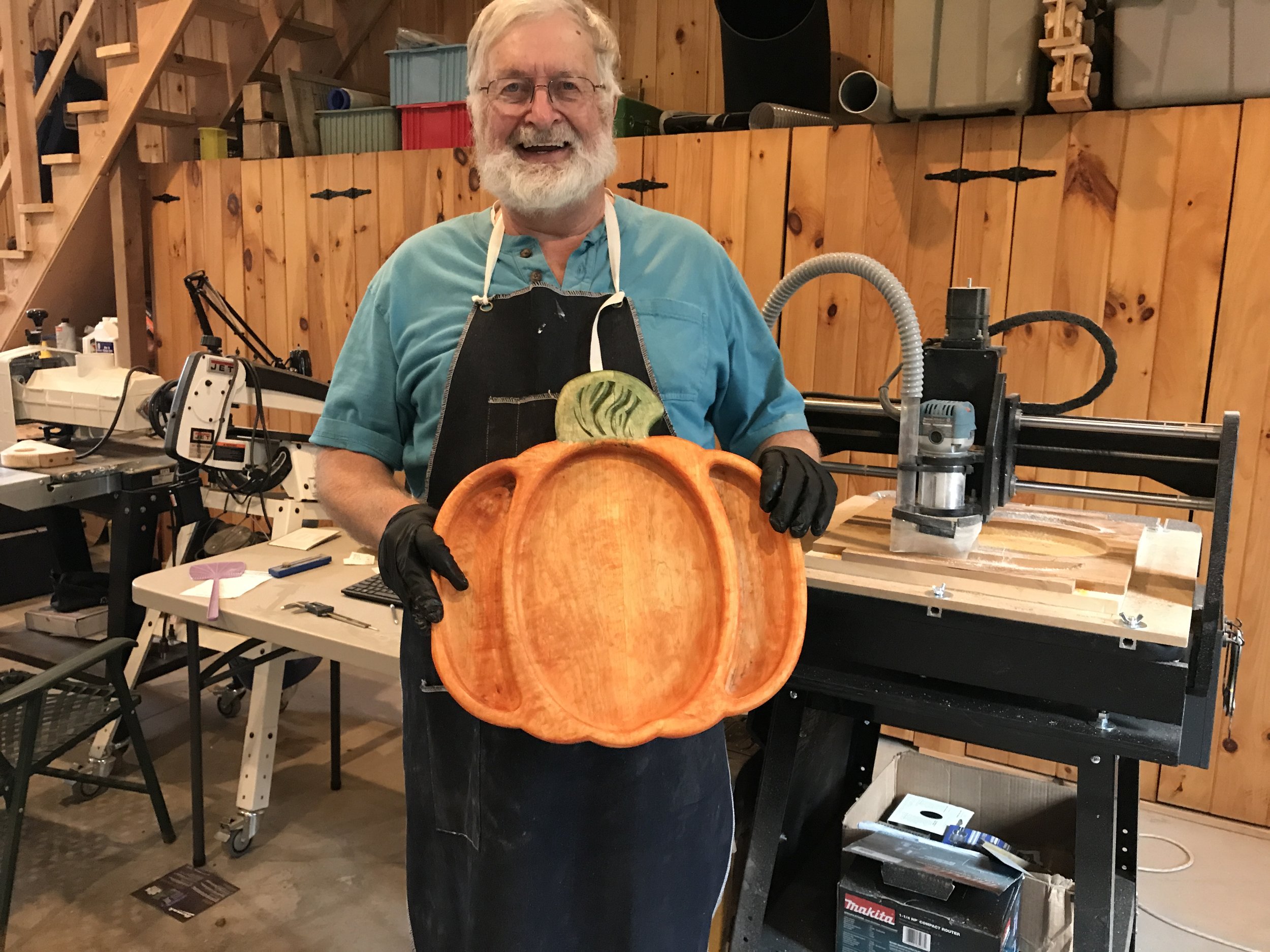
His shop is lined with what he calls “my people”, unique wood carvings that showcase his creativity. Visitors from nearby areas stop by just to see them in person, often commenting that pictures don’t do them justice.
But what really brings Jeff joy? Turning down offers, sometimes huge ones, for his work. Every piece is one-of-a-kind, and he has no interest in selling them. For him, it’s all about the love of the craft.
Why the DWC 2440 Was the Right Choice
After seven years of continuous use, Jeff still considers his DWC 2440 “one of the best purchases I’ve ever made.” The machine’s reliability and ease of use have made it an essential part of his woodworking journey.
He also gives credit to Digital Wood Carver’s customer support, mentioning that Burl Tichenor and Laney Shaughnessy are the best at what they do.
“ Digital Wood Carver is a great company. Burl Tichenor & Laney Shaughnessy are the very best at what they do “
Sparky's Woodworks Doubles Production with New DWC2636 CNC Machine
A tribute to craftsmanship, from personalized plaques to community honors. Powered by precision CNC technology, delivering quality from passion to profession.
Sparky's Woodworks, owned by James Sparks, is a thriving business located in Fletcher, Missouri, USA. Specializing in high-quality precision carved signs, gifts, and more for both homes and businesses, Sparky's Woodworks has built a reputation for craftsmanship and attention to detail. The company’s online presence is solid, with an active store and social media showcasing their finely crafted products.
The Challenge:
James had been using a DWC2440 CNC machine for over four years to produce a wide range of precision carvings.
“Ordered our DWC2440 in January 2020 and picked it up in February at the Woodworking Show in Collinsville, IL. It’s been slamming ever since! Started in our basement and added a new shop building in 2022. Yesterday, just in time for our 5th birthday, we became a 2-DWC shop. Spent today tidying up after delivery day chaos and learning the new machine with Laney. Back in business soon with double the production capacity. Super-stoked and a happy DWC customer. Thanks, Laney, Burl, & Jim! Cheers to the next 5 years!”
While the machine served him well, James found himself reaching the limits of its capacity and efficiency, especially as his business grew. To increase his production capacity, improve efficiency, and meet demand, James needed a machine that could handle larger volumes and more complex tasks.
The Solution:
After careful consideration, James upgraded his equipment by purchasing the DWC2636 CNC machine. The larger, more powerful machine promised to provide the speed and reliability James needed to increase his production.
“I had my 2440 for about 4.5 years before adding a 2636. I had sort of gotten set in my ways of doing things, so it came as a surprise when Laney showed me a different way of surfacing the spoilboard when we set up my 2636. Instead of going around in a square pattern cutting in all directions using a pocket cut, we did profile cuts on single lines so the machine only cut in one direction.”
Despite being familiar with his previous DWC2440, James found the new DWC2636 offered faster speeds, smoother cuts, and a significant boost in his ability to handle larger jobs with ease.
“I started with a batch of 25 small food boards (9x14) as my first test project. The machine made light work of them, completing the intricate v-carve with impressive speed and precision.”
“My first carve on DWC2636 sitting on top of the next 25 carves. The 2636 made light work of those food boards! Fast, clean, consistent. Super stoked.” - James shared
Benefits:
Increased Production Capacity
The addition of the DWC2636 allowed James to run both machines simultaneously, effectively doubling his production capacity.
“With two machines now, I can run them both at once, doubling my output. I'm more than happy with my decision to upgrade to the DWC2636!”
This upgrade was especially critical as James had recently seen a surge in orders. With two CNC machines in operation, he could fulfill more customer requests in a fraction of the time it previously took.
Improved Efficiency and Speed
James noticed a dramatic increase in the machine’s cutting speed and overall efficiency.
“I had no idea my bits were capable of moving so fast! Sometimes it’s scary. ‘Quiet’ is not a word I’d use to describe the 2636. I thought the 2440 was loud. The 2440 sounds almost silent compared to the 2636 when it’s running. It’s cool though, it sounds like an industrial machine.”
“When it’s sitting still, the 2636 is quieter than my 2440—you can barely hear the fan and water pump. But as soon as the carving starts, you can’t even hear the 2440 running over the 2636. I guess it’s just the nature of the screw drives and the more powerful motors.”
The surfacing and roughing processes, which typically took several hours on the 2440, were completed in much less time on the DWC2636.
Spark’s woodwork project with DWC2636
More Consistent Results
James quickly found that the DWC2636 provided more consistent results across the board. Whether he was carving food boards or precision signs, the machine delivered a higher level of accuracy and fewer imperfections in the final product. This consistency helped increase customer satisfaction and repeat business.
Ease of Setup and Use
Though James had already been using a CNC machine for years, the transition to the DWC2636 was seamless, thanks to the helpful guidance from Laney and the user-friendly setup.
“Things aren’t where they usually are, I’m tripping over stuff, but I’m loving having both machines running at once.”
Conclusion
Sparky’s Woodworks has seen substantial growth and efficiency improvements since adding the DWC2636 to their shop. The larger, faster machine has allowed James to take on more work, improve production times, and deliver even better products to his customers.
The upgrade to the DWC2636 has proven to be a valuable investment, ensuring that Sparky’s Woodworks is prepared to meet growing demand and continue delivering exceptional quality for years to come.
Related Products
DWC2636
From $6,499
YOU may also LIKEs THIS
7,000+ CNC-Made Plaques in 6 Years?! The Rise of Wyckoff's Workshop
A tribute to craftsmanship, from personalized plaques to community honors. Powered by precision CNC technology, delivering quality from passion to profession.
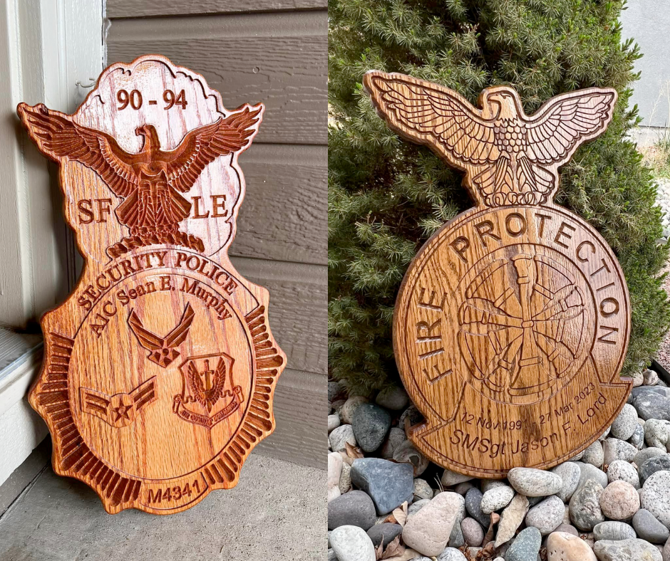
In the heart of Colorado Springs, amid the picturesque scenery of the Rocky Mountains, lies Wyckoff's Workshop—a testament to the vision and dedication of Brandon Gene, a retired USAF TSgt.
From intricately carved plaques honoring first responders to personalized signs, Wyckoff's Workshop started with just one plaque.
Making Headlines: A Community's Tribute
Wyckoff's Workshop has garnered attention beyond its local community, making headlines on both KKTV11 News and FOX 31 News out of Denver. The workshop has been involved in crafting heartfelt tribute to fallen police officers. Brandon and his team ensured that their memory and bravery would endure
Discovering Digital Wood Carver:
Seven years ago, Brandon embarked on a transformative journey when he invested in DWC's CNC router technology. Reflecting on this pivotal decision, he fondly recalls, "First, an appreciation to DWC Laney Shaughnessy and Burl Tichenor for making the best CNC & Support team there is!" This partnership marked the start of Wyckoff's Workshop's growth. With DWC's expertise and reliable machinery at his disposal, Brandon could bring his creative visions to life with unparalleled precision and efficiency.
From Passion to Profession:
What began as a humble hobby soon blossomed into a thriving business venture for Brandon. Over the years, Wyckoff's Workshop has produced over 5,000 meticulously crafted plaques, garnering a loyal clientele both locally and internationally. Brandon proudly reflects, "From plaque 1 to just hitting our 7k in production and sales in 6 years!" Such remarkable growth is a testament to Brandon's dedication and the impact of CNC technology in woodworking.
Quality Craftsmanship, Powered by Digital wood carver:
Every piece, whether it's a custom military plaque or a POW MIA tribute, is made with meticulous attention to detail and heartfelt dedication. Brandon's passion for excellence is palpable in his words: "We pour blood, sweat, and tears into each of our creations and should be sold as such." With Digital Wood Carver's CNC routers (DWC2440), Brandon has the precision and reliability needed to deliver exceptional quality with every project, ensuring that each piece leaving his workshop is a true work of art.
Navigating Business Growth:
As Wyckoff's Workshop continued to flourish, Brandon encountered the challenge of scaling his business while maintaining the integrity of his craft. Drawing from his wealth of experience, he shares invaluable insights: "If you know what you are worth, go get what you are worth and do not let anyone tell you otherwise." Brandon's strategic approach to pricing and marketing, coupled with DWC's state-of-the-art technology, propelled his business to new heights, cementing its status as an industry leader in woodworking craftsmanship.
A Community of Support:
Beyond providing cutting-edge machinery, DWC fosters a vibrant community of woodworkers—a community that Brandon is proud to be a part of. His active involvement in the Digital Wood Carver Owners Group has provided him with invaluable support and camaraderie. Reflecting on the importance of community, he remarks, "22K followers later and over $650k in sales in the last 4 years here I am still making what I want and promoting a quality product."
Conclusion:
The remarkable success of Wyckoff's Workshop is a testament to the power of passion, perseverance, and collaboration. Brandon Gene's journey from a retired Airman to an entrepreneur serves as an inspiration to woodworkers worldwide. And behind every masterpiece crafted at Wyckoff's Workshop lies the precision and reliability of Digital Wood Carver, empowering artisans like Brandon to turn their dreams into reality.
Related Products
YOU may also LIKEs THIS
From Lake Maps to Wood Boards: Kim's Lucrative Business Journey at Maple Works Designs
Turning beloved lakes into cherished gift boards, Kim's Custom Lake Map Boards with DWC1824 CNC have fostered a successful global business beyond Canada's borders
Step into the world of Maple Works Designs, where Kim Herrler blends artistry with craftsmanship to create custom lake map boards that delight customers worldwide. With her DWC1824 CNC router, Kim has transformed her passion for woodworking into a thriving business, inspiring others to explore the possibilities of CNC technology in the woodworking industry.
The Roots of Maple Works Designs
In Uxbridge, Kim started woodworking in high school two decades ago. Recognizing the advancing tide of digital technology, Kim seized upon the opportunity to blend traditional woodworking methods with contemporary CNC router technology.
In addition to her well-received lake map boards, Kim's portfolio boasts an assortment of other creations, including bespoke furniture, personalized engravings, and intricate epoxy inlays.
Crafting Personalized Lake Map Boards
At Maple Works Designs, every piece tells a story. Kim Herrler meticulously crafts custom lake map boards, infusing each with the essence of cherished waterways. Take, for example, the breathtaking Kennisis Lake map board, intricately engraved with the shorelines and depths of this locale.
With the DWC1824 CNC router as her tool of choice, Kim skillfully navigates the intricate contours of lakes and rivers, transforming raw wood into personalized treasures for her clients. Whether it's the tranquil shores of Little Sebago Lake or the majestic expanse of Roven Lake, each custom map board captures the unique beauty and memories of these cherished destinations.
The Process Behind Crafting Lake Map Boards
Using the DWC1824 CNC router, Kim brings her clients' visions to life with precision and finesse. From selecting premium ambrosia maple to engraving intricate designs, every step of the process reflects Kim's commitment to quality craftsmanship. With its user-friendly interface and robust construction, the DWC1824 streamlines the carving process, allowing Kim to focus on the creative aspect of her work.
A Personal Touch
What sets Maple Works Designs lake map boards apart is the attention to detail. Each board is meticulously crafted, from the hand-painted lettering to the custom epoxy resin fills. These personalized touches not only enhance the aesthetic appeal of the boards but also create a deeper emotional connection for Kim's clients, who see their memories and experiences reflected in every piece.
Customer Satisfaction and Beyond
Kim's dedication to customer satisfaction extends beyond the Mount Albert, Ontario. Thanks to the global reach of the internet, Maple Works Designs lake map boards have found homes in cottages, lake houses, and vacation spots around the world. Check it out Kim’s recent works and the process video on instagram @mapleworksdesigns.
Whether it's a local resident or an international enthusiast, Kim's creations resonate with individuals who appreciate the beauty of handcrafted woodworking.
Empowering Creativity with DWC1824
When Kim first ventured into the world of digital woodworking, she approached it with cautious optimism as a beginner CNC router user. However, the DWC1824 CNC router proved to be a game-changer, providing Kim with the tools and confidence to pursue her passion. With its robust construction and intuitive design software, the DWC1824 has become an invaluable asset in Kim's workshop, offering a seamless carving experience and enabling her to explore new creative avenues.
Its compact size and easy-to-use features make it the perfect companion for both novice woodworkers and seasoned professionals alike, allowing Kim to elevate her craft and expand her business beyond traditional woodworking practices.
Kim's Experience in the DWC Owner Group
Kim Herrler encountered a problem with her DWC CNC machine. She sought help in the DWC owner group on Facebook, reaching out to fellow DWC CNC owners and Digital Wood Carver's customer service representative.
She asked the group, "I ran a test cut and had very faint lines in my cleaners out section from my end mill. A few minutes later I’m running the same file, same bit, same walnut and the lines are way more noticeable. Not sure why there’s such a difference. Can anyone shed some light and point me in the direction to fix it? I don’t want to engrave the text until it’s smoother and I don’t want to pull it off the machine."
After receiving helpful tips from the group, Kim tried a final pass at 0.02, which reduced the need for sanding. She also received guidance from Laney and other members on properly reconnecting cables to address technical issues like controller malfunctions and inconsistent engraving results.
This experience showcases the helpful community in the DWC owner group and Digital Wood Carver's commitment to providing support to its users.
Looking Ahead:
As Maple Works Designs continues to grow, Kim remains committed to pushing the boundaries of creativity and innovation. With the DWC1824 CNC router by her side, the possibilities are endless.
Conclusion
Maple Works Designs and Kim Herrler stand as a testament to the fusion of tradition and technology in woodworking. With a commitment to quality craftsmanship and community support, Kim's journey inspires authenticity and innovation. Stay tuned for upcoming case studies that delve deeper into Maple Works Designs' stories. For more content and inspiration, check the link below.
Related Products
YOU may also LIKEs THIS
Wooden Wonders by Steve: Crafting Custom Creations with Digital Wood Carver's CNC Routers
Nestled in the heart of Brighton, Michigan, Wooden Wonders by Steve is a thriving custom furniture and woodworking shop that has been captivating clients with its unique and meticulously crafted pieces since 2016.
Steven, the owner and mastermind behind this creative endeavor, has seamlessly integrated Digital Wood Carver's CNC routers into his workshop, enabling him to push the boundaries of his craft and bring his artistic visions to life with unparalleled precision and efficiency.
Why a CNC Router?
Before discovering the world of CNC routers, Steve faced limitations in the complexity and intricacy of his designs. Traditional woodworking techniques, while impressive, often fell short when it came to realizing his most ambitious and intricate visions. This led him on a quest to find a solution that would elevate his creations to new heights.
Finding the Best CNC Router
In his search for the perfect CNC router, Steven came across Digital Wood Carver and was immediately drawn to their reputation for quality and customer support. The company's extensive range of hobbyist to commercial CNC routers, coupled with their commitment to user-friendly software and comprehensive training, made them an ideal choice for Steven's evolving needs.
Steven’s first DWC CNC router (DWC2440)
The Benefits of a Digital Wood Carver CNC Router
Steven's journey with Digital Wood Carver began in 2018 when he acquired the DWC2440 PRO CNC Router. This versatile CNC allowed him to carve intricate designs with more accuracy, enabling him to create stunning pieces like custom tables, signs, chairs, and more.
Impressed by the capabilities of his first CNC router, Steve recently upgraded to the DWC2636 HD CNC Router, further expanding his creative horizons.
“This will allow me to do so much more!” Steve says.
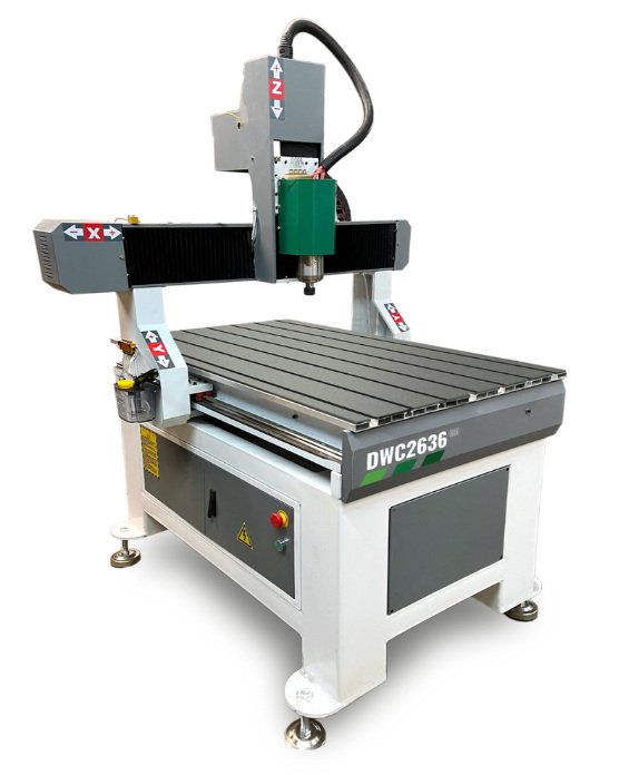
With the DWC2636, Steven can tackle even larger projects with ease, thanks to its impressive 26" x 36" x 7" cutting area and a powerful 2.2KW (3HP) liquid-cooled spindle.
“Introducing our newest employee (DWC2636) “ CPL CARVER “ - Steven
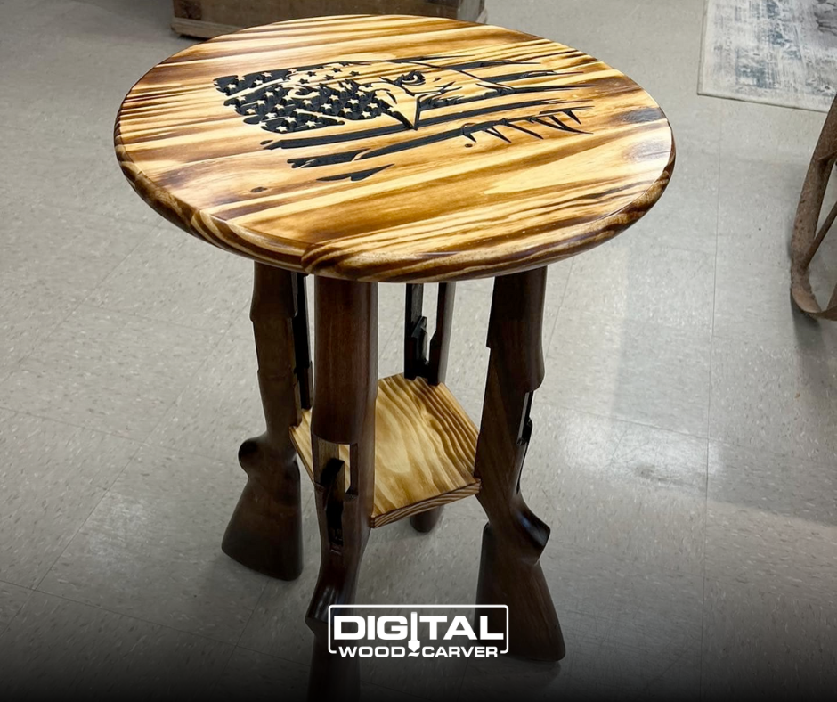
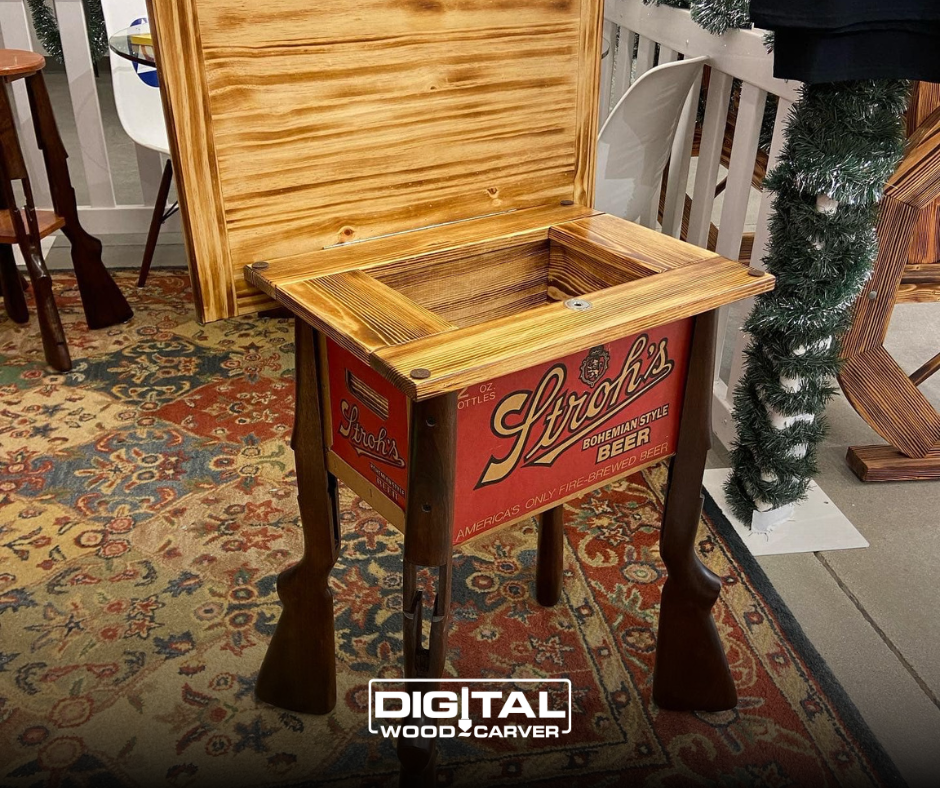
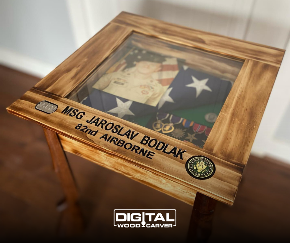
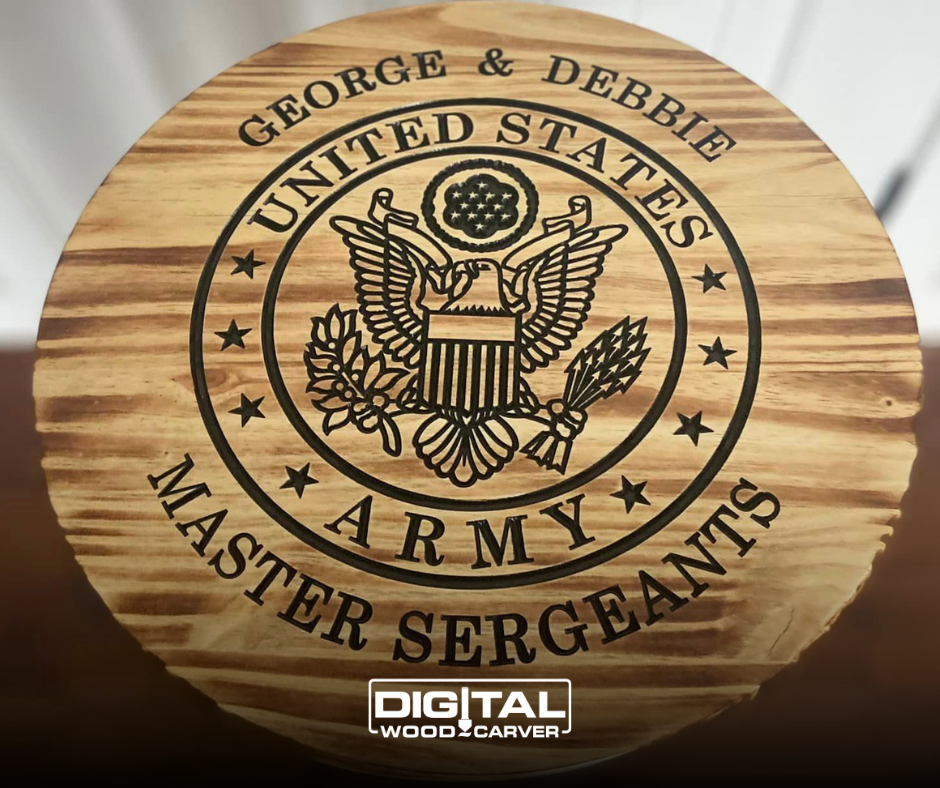
From intricate table bases crafted from vintage Remington rifle shipping crates to a breathtaking D-Day anniversary table auctioned at the National NRA meeting, Steven's creations have garnered admiration and praise from clients and fellow woodworkers alike.
CNC Customer Service Experience
Throughout his journey with Digital Wood Carver, Steven has been consistently impressed by the company's exceptional customer support.
“I will have to say the service at Digital Wood Carver is outstanding!!! They have been incredibly helpful getting our new DWC 2636 up and running”
From the initial setup and training to troubleshooting and guidance, the team at Digital Wood Carver has been readily available to address any concerns or queries, ensuring a seamless and productive experience.
Beyond his remarkable woodworking skills, Steve's passion for honoring historical artifacts and supporting noble causes shines through in his work. His creations often incorporate repurposed materials, such as surplus WWII M1 Garand stocks, breathing new life into these relics while preserving their rich history.
Additionally, Steven has generously donated pieces like the M1 table (the first table in the gallery above) to to support the mission at Tools For Veterans.
How to get started with CNC woodworking
Steven's story with Digital Wood Carver is a testament to the power of combining creativity, craftsmanship, and advanced technology.
Whether you're a hobbyist seeking to explore the world of CNC routing or a professional woodworker looking to take your business to new heights, Digital Wood Carver's range of CNC routers and unparalleled customer support can help you unlock your full potential.
Explore their offerings and read reviews to discover how their beginner to commercial CNC routers can elevate your woodworking projects to new levels of excellence.
Conclusion:
As we conclude this glimpse into the world of Wooden Wonders by Steve and the transformative impact of Digital Wood Carver's CNC routers, we invite you to stay tuned for our next case study. Explore how innovative technology continues to shape and redefine the boundaries of craftsmanship, as we delve deeper into the stories of artisans like Steven who are pushing the limits of what's possible in woodworking.
Related Products
YOU MIGHT LIKE THIS
Photographer Discovers CNC Wood Carving with Digital Wood Carver
Joe DeFabis turns to Digital Wood Carver's CNC routers and support after retiring from award-winning photography career.
Joe DeFabis turns to Digital Wood Carver's CNC routers and support after retiring from award-winning photography career.
Introduction:
Joe DeFabis, a celebrated photographer from Indianapolis, has spent over three decades capturing life's most precious moments through his lens. However, in recent years, he has embarked on a new creative endeavor – CNC woodworking. With the help of Digital Wood Carver's top-of-the-line CNC routers, Joe has unlocked a world of possibilities, allowing him to bring his artistic visions to life in a new and exciting medium.
The Challenge:
With no prior experience in CNC woodworking, Joe faced the daunting task of navigating a complex and unfamiliar territory. As a self-proclaimed novice in the field, he knew he needed a reliable and user-friendly solution that could guide him through the learning curve.
Discovering Digital Wood Carver:
In his search for the perfect CNC router, Joe was drawn to Digital Wood Carver's reputation for exceptional customer support and user-friendly products. The company's positive reviews, particularly regarding their responsive and knowledgeable team, solidified his decision to invest in a DWC 2440 CNC router.
The Solution:
Joe's journey with the DWC 2440 CNC router has been nothing short of remarkable. Despite his initial trepidation, the machine's intuitive design and the unwavering support from Digital Wood Carver's team have empowered him to create stunning woodcarving projects. As he recounts,
"I have found that the DWC 2440 is a great machine, and the service and support is A++++ being a new owner and never having carved before, I had to rely on DWC support for a few questions after I began carving. Laney was always patient, knowledgeable, and helpful."
Support Experience:
Joe's experience with Digital Wood Carver's customer support team has been truly exceptional. He singles out Laney as a standout member, praising his patience, knowledge, and willingness to assist him throughout his learning process. "Laney is a true asset for DWC," Joe affirms, underscoring the company's commitment to ensuring its customers' success.
Personal Touch:
Beyond his newfound passion for CNC woodworking, Joe's life has been a testament to his creative spirit and dedication to his craft. As a four-time winner of the "IPPG Wedding Photographer of the Year" Award and a five-time recipient of the "Best Album" award, his accomplishments in the field of photography are truly remarkable. Joe's love for motorsports and landscape photography has also fueled his artistic journey, allowing him to capture the beauty and excitement of the world around him.
Conclusion:
Joe DeFabis's story is a testament to the power of embracing new challenges and the transformative potential of Digital Wood Carver's CNC routers. Whether you're a seasoned woodworker or a beginner like Joe, Digital Wood Carver offers a range of hobbyist to commercial CNC routers, designed to empower you on your creative journey. With a commitment to exceptional customer support and a dedication to helping users succeed, Digital Wood Carver stands out as a trusted partner for anyone seeking to unlock their artistic potential in the world of CNC woodworking.
Related Products
YOU MIGHT LIKE THIS
3 Unique Wall Art Concepts and Ideas | A Vectric Tutorial
Running out of cool CNC project ideas? Let us introduce you to three unique wall art concepts that you may have never heard before!
In this tutorial, we’ll walk you through three wall art ideas to spice up your CNC projects—Silhouette wall art, Three Panel wall art, and Parametric wall art.
Running out of cool CNC project ideas? Let us introduce you to three unique wall art concepts that you may have never heard before!
In this tutorial, we’ll walk you through three wall art ideas to spice up your CNC projects—Silhouette wall art, Three Panel wall art, and Parametric wall art. We’ve also included a quick step-by-step process on how to create the first two concepts using any Vectric Software.
Don’t forget to hit the SUBSCRIBE button to keep up with our bi-weekly LIVE Vectric classes!
Silhouette Wall Art
The first concept that you can explore is silhouette wall art.
As the name suggests, it’s a carved out image of a thing, animal, or person’s silhouette. This creates simple yet elegant wall decor for your home or office.You can carve out your favorite artist’s silhouette, or design your own concept!
How to Create a Silhouette Wall Art with a CNC
1.Create a Design
Import your chosen silhouette image onto your job setup. You can play around and add designs and text as desired. Then, you create a rectangle over the entire project and offset it inwards to create a border for your design.
2. Trace Bitmap
Now you have to turn the image into a vector. To do that, you need to use the Trace Bitmap tool and decide whether to use Color Tracing or Black/White Tracing.
Color Tracing will ask you to tick all the colors you want to fill in. So for a black and white image, you’ll want to tick the gray shades as well to make sure it catches as many details.
On the other hand, the Black/White Tracing will convert your image into a purely black and white image. Then, all you need to do is adjust the slidebar until you achieve your desired amount of detail.
Lastly, you adjust the Corner Fit and Noise Filter to either sharpen the image or leave more room for carving as preferred. To check for any unwanted lines or tiny areas, you can always turn the image layer off to view the vector as it is.
Want to start a CNC wood carving business from home?
Download our 18-page guide packed with tips and advice from successful customers who have already made it happen.
Take the first step towards turning your passion into a profitable business!
3.Create a Pocket Cut Toolpath
Select your vectors, text, and border and open the Pocket Cut toolpath. You can do a shallow or deep cut depending on your preference.
However, ideally you shouldn’t cut deeper than ⅛-inch. Opting for a shallow cut will give your wall art a sleeker look! Otherwise, you might lose the visualization and end up with just really deep holes. We’ll also use a combination of a ¼-inch, ⅛-inch, and 1/16-inch end mill to highlight as much detail as possible.
Calculate the toolpath and review the toolpath for every end mill to check if everything looks good. If yes, then you’re ready to go!
Three Panel Wall Art
If you want to create something large that would sit nicely behind the couch or on a large vacant wall, then you can also create a three panel wall art.
Connect with Digital Wood Carver
A three panel wall art is made up of three separate panels that are either arranged vertically or horizontally. It’s perfect for those with large CNC machines as you can just run the project in one sitting. Alternatively, you can carve it per panel if you have a smaller machine.
How to Make a Three Panel Wall Art with a CNC
Create a Design
Like how you start any project, create your preferred job setup and add in some images, text, and a border.
2. Trace Bitmap
Open the Trace Bitmap Tool and select Black/White Tracing. Drag the slidebar to a 0.75 threshold, and adjust the Corner Fit and Noise Filter as desired. Turn off the image layer, and you should have a traced vector of your design.
Now, with this type of design, the outline of the trees, mountain and the border will be the wood area—everything else will be carved away.
If you want a more unified look, you can size up the vector image at the center so it intersects with the border. Then, you clear all vectors outside the border, this way, the border becomes a part of the vector design!
3.Split into Sections
Now you can always proceed to creating the toolpaths if you think the design already looks good. However, since we’re creating a Three Panel Wall Art, we need to divide the design into three sections.
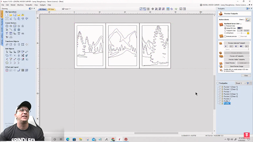
To do this, all you have to do is create a rectangle over the entire design, which will serve as your boundary, and another 2-inches-wide rectangle as the divider. This leaves room for the CNC to cut through the middle of the dividers.
Hold down the CTRL key, and copy the rectangle so you have two of them. Select the two dividers and the boundary and space them equally horizontally using the Alignment Tools. This way, your panels are exactly as large as the other.
Using the Scissors tool, cut out the unwanted vectors. Then, you’ll want to draw another rectangle over each panel design, offset it outwards by 2-inches to get that perfect panel border and group them together. Do this for all three panels so you’re left with three panel designs.
Then, move the first panel to the left by 1.06-inch to leave a gap between the first two panels. Do the same for the third panel, but towards the right.
Now you’re ready to create your toolpath!
4.Create a Profile Cut Toolpath
To finish up the design, select all vectors and cut inside the vectors with a depth of ¾-inch using a ⅛-inch end mill. Calculate the toolpath, and you should now have a perfect design for your three panel wall art!
Pro Tip: Always use an end mill that can cut through your material.
Parametric Wall Art
Last but not least, we have the Parametric Wall Art.
Parametric wall art is one of the most popular styles of wall art. They come in sophisticated parametric wavelength designs and they look good in almost any type of space.
For this reason, there is a pool of buyers willing to spend for these types of wall art. They can cost hundreds to thousands of dollars, yet are generally simple to make. This makes them a great ‘money-maker’ for CNC enthusiasts!
What is Parametric Wall Art Made of?
Parametric wall art are made out of wood. You can use MDF, plywood, or solid wood. Parametric designs can be created with the Vectric Aspire software. Alternatively, you can also purchase cut files from artists like ParametricArtWood on Etsy.
A small investment of $15-16 and you can earn a few hundred dollars from your works!
Unlike the previous two wall art concepts, you can only create a Parametric Wall Art design with Vectric Aspire. For a quick runthrough of how to create a Parametric design, you can view Laney’s quick tutorial by the end of the Wall Art Concepts and Ideas session.
For a more proactive and full step-by-step walkthrough on how to work around the three different wall art ideas we introduced, check out Laney’s LIVE Vectric Tutorial on Wall Art Concepts and Ideas.
Don’t forget to like and Subscribe to the SpindleTV channel to keep up with the latest updates and to join our LIVE Vectric classes every other week.
Browse CNCs
From hobbyist to commercial and everything in-between.
A Look at 3 Approaches to Text-on-Text Designs
Want to explore Text-on-Text designs? Take a look at these three approaches you can use to get a great result!
For this guide, we’ll be introducing you to three different ways to design a text-on-text project.
That includes the Triple Layer Approach,
the Four Layer Approach,
and the Modeled Stacked Text Approach (exclusive for Vectric Aspire Software).
Want to explore Text-on-Text designs? Take a look at these three approaches you can use to get a great result!
For this guide, we’ll be introducing you to three different ways to design a text-on-text project. That includes:
The Triple Layer Approach
The Four Layer Approach
The Modeled Stacked Text Approach (exclusive for Vectric Aspire Software)
For a detailed run of every process, watch Laney’s LIVE tutorial video on SpindleTV.
Triple Layer Approach
1. Create Your Layers.
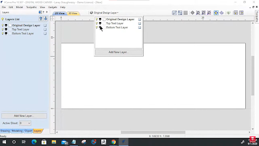
Right off the bat when you’re happy with your job setup, we are going to start by organizing your layers. From the top of the view bar, you can see a drop down list where you can access and manage your layers.
You’ll be needing three layers for this approach so you’ll have to rename your current layer and add two more.
Here are the layers you’ll need:
Original Layer
Top Text Layer
Bottom Layer
Make sure that your Original Design Layer is active. You’ll know it is when its name is in bold. Also, since we’ll be working on the original design layer first, we’ll need to turn off the other two layers for now.
After that, let’s create our project border using the Draw Rectangle Tool. We just drag over the entire project area, and we offset it inwards. Type in how thick you want your border to be on the Distance box and click Offset.
2. Add Text
Next, add in your text.
For a text-on-text project, it’s best to start with the text at the back before adding in the text that you want to have in front. In this case, we’ll have SpindleTV at the back, Laney Shaughnessey in front, and a quick tagline at the bottom.
Want to start a CNC wood carving business from home?
Download our 18-page guide packed with tips and advice from successful customers who have already made it happen.
Take the first step towards turning your passion into a profitable business!
Choose your preferred font and make sure to keep it balanced on your board using the Alignment tools.
For the tagline on the bottom, we want the protruding rather than the carved effect. So, we’ll create a rectangle boundary around it, and offset it outwards to ⅛ of an inch so that it doesn’t get carved away.
3. Separate the Layers
Now that your design is ready, you can now copy each element into their designated layer.
For the Bottom Layer, select the text at the further back, the border and the tagline. Right click and Copy to Layer – Bottom Layer.For the Top Text Layer, select the front text and the border and do the same except copy it to the Front Text Layer.
After separating the vectors, you can work on each layer separately by turning off the other layers.
Top Text Layer
When using script typefaces, you might encounter overlapping lines in your text. You’re going to have to clean up those extra vectors since we don’t want the machine to run through the same area twice.
Bottom Text Layer
Offset the bottom text inward based on the VBit that you will use. This is how deep you want your machine to cut through your material. You can check out how Laney finds the exact measurement using the Measure Tool in the tutorial.
In this case, we’ll offset it by 0.0722. Make sure that you delete the original and don’t worry if it looks too skinny, it’ll look exactly like how it was earlier when it’s carved.
Finally, reselect your back text and group it together so the software treats it as one vector.
Connect with Digital Wood Carver
4.Weld the Back and Front Text
When you’re done with the back text, you can now go back to the front text and copy it onto the Back Text Layer and convert it into curves. This way, it’s much easier to weld the texts together.
Select the two texts and weld the two together using the Weld Tool. Turn on the Front Text Layer, and now you’re set to run the toolpath.
5.Run the Toolpath
Starting with the Top Text Layer, set the Start Depth to 0, Flat Depth to ⅛ inch, 60 degree VBit, and a Flat Area Clarence Tool of ¼ and ⅛ inch End Mill. Tick Raster Cut, and calculate.
For the Bottom Text Layer, select the border, the welded text and the inner border of the tagline.
Then, we create a VCarve Toolpath with the same tools as the Top Text except we’ll have a Flat Depth of ¼ inch.
Calculate toolpath to preview.
Onto our last toolpath, select the tagline and outer boundary of the tagline.
Then, set the Start Depth and Flat Depth to ⅛ inch, use an End Mill of ⅛ inch as well, tick Raster cut, and calculate.
Always look out for any overlapping lines or unprotected vectors. Don’t be afraid to make adjustments!
Four Layer Approach
Another way you can go about Text-on-Text Design is the Four Layer Approach. As the name implies, it has four layers:
Original Layer
Top Text Layer
Bottom Text Layer
Welded Text Layer
The first few steps for this approach are similar to the Triple Layer Approach:
Create the border
Add the Text
You should have two sets – the first text is for the bottom layer, and the other for the top layer.
After adding the text on the Original Layer, you can now copy each one to their designated layer. Top text plus the border for the Top Text Layer, and ONLY the back text (no border!) for the Bottom Text Layer.
1.Working on the Top and Bottom Text Layers
Turn off the Original Layer, activate the Top Text Layer, and determine your desired text height and VBit. In our case, we’ll be going for a 1/8 inch pocket depth, a 60 degree VBit, and a 0.058 offset for both the top and bottom text.
If your text happens to be a script font, make sure to clean up overlapping lines. You could use the Scissor Tool for this, but the quickest would be to weld the text together.
After welding, copy the welded Top Text and paste it onto the Welded Layer.
For the bottom text, all you need to do is activate the bottom text layer, group the vectors together and copy it onto the Welded Text Layer.
2. Working on the Welded Layer
Offset the welded text copied earlier outward by 0.058 and make sure to delete the original vector. Then, group the offset vectors together. There should be no sharp corners and the original border should be deleted.
Then, offset the border inward by the same magic number, 0.058, and delete the original vector. This will make the text look a lot thicker, but it gets better. Just trust the process!
Select the welded top and bottom text and weld the two groups together.
3.Creating the Toolpath
The toolpathing will be a bit different for this approach.
Starting with the Top Text Layer, let’s set the Start Depth to 0, Flat Depth to 0.1, and End Mills to ⅛ inch and ¼ inch. Rename the Toolpath created and Calculate.
Now, let’s hop onto the Welded Text Layer. For this Toolpath, everything stays the same except for the Start Depth which will now become 0.1 which was where the previous Toolpath left off. This way, you can carve just as deep as you initially wanted.
Rename the Toolpath, calculate, and preview.
Modeled Stacked Text Approach
For those who use the Vectric Aspire Software, another approach you could do is the Modeled Text Approach. Preliminaries are exactly the same as the previous approaches—setup the project, create your border, and add in the text. However, you’ll notice some changes later in the process!
For that reason, we’re repeating the same design as the Triple Layer Approach.
Pro Tip: Always use Very High or Extremely High modeling resolution for your projects for the best results.
Firstly, let’s get the text back to its original places and typeface. Make sure they’re centered and when ready, we can jump straight into the good part–Modeling.
1. Modeling the Components
For easier viewing, go to a 2D Split View and let’s start with modeling the Bottom Text. In this stage, you have the freedom to play with your model however you want. So don’t feel obliged to follow every number on this tutorial—this is just a guide after all!
Select the Bottom Text and open the Create Shape tool under the Modeling menu. For the bottom text, we’re looking to create a curved profile at a 90 degree curve, with a base height of ⅛ of an inch.
Tick Limit to Height of 1/16 of an inch for a rounded edge, rename the component, and click Apply. This should automatically reflect on the bottom half of your screen!
Now let’s create a new component for the top text. We do the exact same process here, except we want the top text to be a bit higher than the bottom text. So, we’ll set the Limit to Height to ⅛ of an inch instead and we should have it merged onto the bottom text. When done, rename the component and click Apply.
And lastly, we create another component for the tagline, set the base height to ⅛ inch, limit to 1/32 inch and add it to other components. Rename, and click apply!
2. Add a Draft
When done, you’ll notice that the walls of the texts are far too sharp and straightened–which we don’t want. Thus, we’ll add an angle around it to soften the sides and make it more appealing.
To do so, drag over the three components to select them and Add Draft. You can manually drag to find the best angle. For us, we’re going at a 22 degree angle.
Adding a draft will create a new component that combines all three layers, so now you can turn off the visibility of the other layers and create an out vector boundary around it.
When you’re satisfied, click Apply and you’re ready to create a toolpath!
3.Creating a Toolpath
One thing you have to remember when creating a toolpath for this approach is the height of your material which you can find on your Material Setup. Note this down as this will serve as the basis for how deep you want your machine to cut through.
Clearing Toolpath
Select your border and the outermost boundary you created for your text and click Pocket Toolpath. Set the cut depth to the height of your material, or in this case 0.2813, combine a ¼ and ⅛ inch end mills, and tick Raster cut. Then, you can rename the toolpath, calculate, and preview.
Roughing Toolpath
Now let’s select the 3D Roughing Toolpath and tick Model Boundary. Sticking on the ¼ inch End Mill, we want the boundary offset to be at ⅛ inch. We’ll also want to set a Machining Allowance of 0.4 and a Z Level Raster, this way, your vectors blend in nicely.
Rename the toolpath, calculate, and preview. It might not look like much right now but having a rough cut makes a huge difference.
Finishing Toolpath
To finish up, let’s jump into the Finish Machining Toolpath and use a 1/16 inch Tapered Ball Nose. Set the Machining limit to Model Boundary at an offset of ⅛ inch and Raster. Rename the toolpath and calculate.
And that’s a wrap! Make sure to save both your design and toolpaths so you won’t have to repeat the process every time you do a similar project. To follow through the entire step-by-step process with Laney, just visit the full tutorial on SpindleTV.
Don’t forget to like and Subscribe to the SpindleTV channel to keep up with the latest updates and to join our LIVE Vectric classes every other week.
Browse CNCs
From hobbyist to commercial and everything in-between.
Vectric Tutorial: How to Create a 3D Terrain Map
Get busy this summer with another cool CNC project! This time, learn how to create a 3D Terrain Map using VCarve Pro and Desktop.
This 3D terrain map tutorial will
outline all the important steps during the process including the basics when working with terrain satellite images.
Get busy this summer with another cool CNC project! This time, learn how to create a 3D Terrain Map using VCarve Pro and Desktop.
This 3D terrain map tutorial will outline all the important steps during the process including the basics when working with terrain satellite images. Think file types, sources, and more! A detailed step-by-step process is also accessible on SpindleTV for your reference.
What is a 3D Terrain Map?
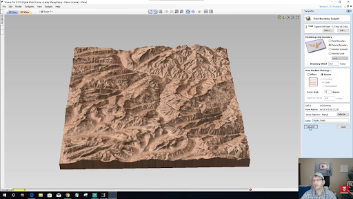
Before anything else, a 3D terrain map visualizes the height and shape of terrains in three dimensions. It can come as a digital image or 3D model and it’s mostly used for environmental management, urban planning, military operations, and so on.
Aesthetic-wise, a 3D terrain map is a cool indoor decoration or gift too! You can create mini 3D models to give as a gift to a hiker friend or create your own ‘travel corner’ at home where you show off models of places you’ve traveled to before.
Perfect for crafters looking for a unique CNC project to get busy over during the weekend!
How to Create a 3D Terrain Map
1. Find a 3D Terrain Map ImagE
3D terrain map images are harder to find than regular photos because they’re not captured in a ‘normal’ way. Rather than cameras or cellphones, they’re created using complex techniques like aerial photogrammetry, satellite imaging, and Light Detection and Ranging (LiDAR).
That’s why satellite images also come in various file formats which will matter later as we go through the process of creating a CNC 3D Terrain Map.
OBJ and STL - The most recommended 3D model file that is compatible with Vectric software
DEM - larger satellite-type files that need to be converted to be used on Vectric software. The data is very taxing as well for regular computers.
Greyscale images - height map images—not just black and white images! Can be used with Vectric Aspire only.
Geotiff
https://touchterrain.geol.iastate.edu/ is one of the specialized websites where you can find 3D terrain map images for free. It covers almost every corner of the world and all you have to do is type down the place you’re looking for!
It also allows you to control how you see the satellite image. So as seen in the bottom left corner, you have options to adjust the height, the zoom, and the puzzle or how detailed you want the image to appear.
Save your chosen image and it should come into your computer as an OBJ file!
2. Import File
After choosing an image you can start with the Job Setup. Since we’re working on a square image, we’ll use a 12x12-inch large and a 1.5-inch thick as the base. Feel free to work with your usual job setup!
Then, click Import a Component or 3D Model under 3D Modelling tools to transfer the image to your base. It will take a few seconds longer considering the size of the file and as soon as it’s uploaded, you’ll need to size it down and set the Initial Orientation to Front to fix the image.
Want to start a CNC wood carving business from home?
Download our 18-page guide packed with tips and advice from successful customers who have already made it happen.
Take the first step towards turning your passion into a profitable business!
Connect with Digital Wood Carver
3.Create a 3D Roughing Toolpath
If you’re working with a terrain image with a lot of deep valleys and crannies, then you’ll want to start by creating a Roughing Toolpath.
It’s best to use a smaller end mill for this project, preferably a ¼ inch end mill. However, this will take much longer than usual and may not be suitable for those with not much time on their hands. In that case, you can pick larger end mills as long as you’re fine with not having perfect carves on smaller crannies!
Since your image occupies the entire space of your material, tick Machining Boundary as the Machining Limit for the project. Set the Machining Allowance to 0.04, the Roughing Strategy to Z level, and Raster X to cut along the X-axis.
Remember: You’ll need to look for alternative clamping methods for this project since the machine will cut through the entire material. You can use hot glue, double-sided carpet tape, etc.
Name your toolpath, calculate, and preview to check for any needed changes.
4.Create the Finishing Toolpath
Finally, create a toolpath for your finishing cut. Set the tool to a ⅛ inch tapered ball nose end mill to carve through the tiniest details of the terrain. If your image is even more detailed than this one, you can also drop down to a smaller-sized end mill to get the best quality!
Lastly, set the Material Boundary as the Machining limit and tick Raster as the machining strategy. Name your toolpath, calculate, and preview!
On VCarve Pro and Desktop, you can also try to enhance your model by playing around with the Component Properties. Here, you can adjust the Shape Height to emphasize the details or add a zero plane to patch up any holes that may show up on the bottom of your model.
And that sums it up! Hopefully, this guide has given you a better idea on how the whole design process works and how to use Vectric Aspire.
For a full step-by-step walkthrough on how to create a 3D terrain map on CNC, check out Laney’s LIVE Vectric Tutorial on How to Create 3D Terrain Maps where he explores other terrain types as well!
Don’t forget to like and Subscribe to the SpindleTV channel to keep up with the latest updates and to join our LIVE Vectric classes every other week.
Browse CNCs
From hobbyist to commercial and everything in-between.
Vectric Tutorial – A Look at 3 Approaches to Text-on-Text Designs
Want to explore Text-on-Text designs? Take a look at these three approaches you can use to get a great result!
For this guide, we’ll be introducing you to three different ways to design a text-on-text project.
That includes the Triple Layer Approach,
the Four Layer Approach,
and the Modeled Stacked Text Approach (exclusive for Vectric Aspire Software).
Want to explore Text-on-Text designs? Take a look at these three approaches you can use to get a great result!
For this guide, we’ll be introducing you to three different ways to design a text-on-text project.
That includes the Triple Layer Approach,
the Four Layer Approach,
and the Modeled Stacked Text Approach (exclusive for Vectric Aspire Software).
For a detailed run of every process, watch Laney’s LIVE tutorial video on SpindleTV.
Don’t forget to hit the SUBSCRIBE button to keep up with our bi-weekly LIVE Vectric classes!
Let’s get on it!
Triple Layer Approach
1.Create Your Layers
Right off the bat when you’re happy with your job setup, we are going to start by organizing your layers. From the top of the view bar, you can see a drop down list where you can access and manage your layers.
You’ll be needing three layers for this approach so you’ll have to rename your current layer and add two more.
Here are the layers you’ll need:
Original Layer
Top Text Layer
Bottom Layer
Make sure that your Original Design Layer is active. You’ll know it is when its name is in bold. Also, since we’ll be working on the original design layer first, we’ll need to turn off the other two layers for now.
After that, let’s create our project border using the Draw Rectangle Tool. We just drag over the entire project area, and we offset it inwards. Type in how thick you want your border to be on the Distance box and click Offset.
2.Add Text
Next, add in your text. For a text-on-text project, it’s best to start with the text at the back before adding in the text that you want to have in front. In this case, we’ll have SpindleTV at the back, Laney Shaughnessey in front, and a quick tagline at the bottom.
Choose your preferred font and make sure to keep it balanced on your board using the Alignment tools.
For the tagline on the bottom, we want the protruding rather than the carved effect. So, we’ll create a rectangle boundary around it, and offset it outwards to ⅛ of an inch so that it doesn’t get carved away.
3. Separate the Layers
Now that your design is ready, you can now copy each element into their designated layer.
For the Bottom Layer, select the text at the further back, the border and the tagline. Right click and Copy to Layer – Bottom Layer.For the Top Text Layer, select the front text and the border and do the same except copy it to the Front Text Layer.
After separating the vectors, you can work on each layer separately by turning off the other layers.
Top Text Layer
When using script typefaces, you might encounter overlapping lines in your text. You’re going to have to clean up those extra vectors since we don’t want the machine to run through the same area twice.
Bottom Text Layer
Offset the bottom text inward based on the VBit that you will use. This is how deep you want your machine to cut through your material. You can check out how Laney finds the exact measurement using the Measure Tool in the tutorial.
In this case, we’ll offset it by 0.0722. Make sure that you delete the original and don’t worry if it looks too skinny, it’ll look exactly like how it was earlier when it’s carved.
Finally, reselect your back text and group it together so the software treats it as one vector.
Want to start a CNC wood carving business from home?
Download our 18-page guide packed with tips and advice from successful customers who have already made it happen.
Take the first step towards turning your passion into a profitable business!
4.Weld the Back and Front Text
When you’re done with the back text, you can now go back to the front text and copy it onto the Back Text Layer and convert it into curves. This way, it’s much easier to weld the texts together.
Select the two texts and weld the two together using the Weld Tool. Turn on the Front Text Layer, and now you’re set to run the toolpath.
5.Run the Toolpath
Starting with the Top Text Layer, set the Start Depth to 0, Flat Depth to ⅛ inch, 60 degree VBit, and a Flat Area Clarence Tool of ¼ and ⅛ inch End Mill. Tick Raster Cut, and calculate.
For the Bottom Text Layer, select the border, the welded text and the inner border of the tagline. Then, we create a VCarve Toolpath with the same tools as the Top Text except we’ll have a Flat Depth of ¼ inch. Calculate toolpath to preview.
For the Bottom Text Layer, select the border, the welded text and the inner border of the tagline. Then, we create a VCarve Toolpath with the same tools as the Top Text except we’ll have a Flat Depth of ¼ inch. Calculate toolpath to preview.
Connect with Digital Wood Carver
Always look out for any overlapping lines or unprotected vectors. Don’t be afraid to make adjustments!
Four Layer Approach
Another way you can go about Text-on-Text Design is the Four Layer Approach. As the name implies, it has four layers:
Original Layer
Top Text Layer
Bottom Text Layer
Welded Text Layer
The first few steps for this approach are similar to the Triple Layer Approach: 1) Create the border and 2) Add the Text. You should have two sets – the first text is for the bottom layer, and the other for the top layer.
After adding the text on the Original Layer, you can now copy each one to their designated layer. Top text plus the border for the Top Text Layer, and ONLY the back text (no border!) for the Bottom Text Layer.
Working on the Top and Bottom Text Layers
Turn off the Original Layer, activate the Top Text Layer, and determine your desired text height and VBit. In our case, we’ll be going for a 1/8 inch pocket depth, a 60 degree VBit, and a 0.058 offset for both the top and bottom text.
If your text happens to be a script font, make sure to clean up overlapping lines. You could use the Scissor Tool for this, but the quickest would be to weld the text together.
After welding, copy the welded Top Text and paste it onto the Welded Layer.For the bottom text, all you need to do is activate the bottom text layer, group the vectors together and copy it onto the Welded Text Layer.
2.Working on the Welded Layer
Offset the welded text copied earlier outward by 0.058 and make sure to delete the original vector. Then, group the offset vectors together. There should be no sharp corners and the original border should be deleted.
Then, offset the border inward by the same magic number, 0.058, and delete the original vector. This will make the text look a lot thicker, but it gets better. Just trust the process!
Select the welded top and bottom text and weld the two groups together.
3.Creating the Toolpath
Starting with the Top Text Layer, let’s set the Start Depth to 0, Flat Depth to 0.1, and End Mills to ⅛ inch and ¼ inch. Rename the Toolpath created and Calculate.
Now, let’s hop onto the Welded Text Layer. For this Toolpath, everything stays the same except for the Start Depth which will now become 0.1 which was where the previous Toolpath left off. This way, you can carve just as deep as you initially wanted.
Rename the Toolpath, calculate, and preview.
Modeled Stacked Text Approach
For those who use the Vectric Aspire Software, another approach you could do is the Modeled Text Approach. Preliminaries are exactly the same as the previous approaches—setup the project, create your border, and add in the text. However, you’ll notice some changes later in the process!
For that reason, we’re repeating the same design as the Triple Layer Approach.
Pro Tip: Always use Very High or Extremely High modeling resolution for your projects for the best results.
Firstly, let’s get the text back to its original places and typeface. Make sure they’re centered and when ready, we can jump straight into the good part–Modeling.
1.Modeling the Components
For easier viewing, go to a 2D Split View and let’s start with modeling the Bottom Text. In this stage, you have the freedom to play with your model however you want. So don’t feel obliged to follow every number on this tutorial—this is just a guide after all!
Select the Bottom Text and open the Create Shape tool under the Modeling menu. For the bottom text, we’re looking to create a curved profile at a 90 degree curve, with a base height of ⅛ of an inch.
Tick Limit to Height of 1/16 of an inch for a rounded edge, rename the component, and click Apply. This should automatically reflect on the bottom half of your screen!
Now let’s create a new component for the top text. We do the exact same process here, except we want the top text to be a bit higher than the bottom text. So, we’ll set the Limit to Height to ⅛ of an inch instead and we should have it merged onto the bottom text. When done, rename the component and click Apply.
And lastly, we create another component for the tagline, set the base height to ⅛ inch, limit to 1/32 inch and add it to other components. Rename, and click apply!
2.Add a Draft
When done, you’ll notice that the walls of the texts are far too sharp and straightened–which we don’t want. Thus, we’ll add an angle around it to soften the sides and make it more appealing.
To do so, drag over the three components to select them and Add Draft. You can manually drag to find the best angle. For us, we’re going at a 22 degree angle.
Adding a draft will create a new component that combines all three layers, so now you can turn off the visibility of the other layers and create an out vector boundary around it.
When you’re satisfied, click Apply and you’re ready to create a toolpath!
3.Creating a Toolpath
One thing you have to remember when creating a toolpath for this approach is the height of your material which you can find on your Material Setup. Note this down as this will serve as the basis for how deep you want your machine to cut through.
Clearing Toolpath
Select your border and the outermost boundary you created for your text and click Pocket Toolpath. Set the cut depth to the height of your material, or in this case 0.2813, combine a ¼ and ⅛ inch end mills, and tick Raster cut. Then, you can rename the toolpath, calculate, and preview.
Roughing Toolpath
Now let’s select the 3D Roughing Toolpath and tick Model Boundary. Sticking on the ¼ inch End Mill, we want the boundary offset to be at ⅛ inch. We’ll also want to set a Machining Allowance of 0.4 and a Z Level Raster, this way, your vectors blend in nicely.
Rename the toolpath, calculate, and preview. It might not look like much right now but having a rough cut makes a huge difference.
Finishing Toolpath
To finish up, let’s jump into the Finish Machining Toolpath and use a 1/16 inch Tapered Ball Nose. Set the Machining limit to Model Boundary at an offset of ⅛ inch and Raster. Rename the toolpath and calculate.
And that’s a wrap! Make sure to save both your design and toolpaths so you won’t have to repeat the process every time you do a similar project. To follow through the entire step-by-step process with Laney, just visit the full tutorial on SpindleTV
Don’t forget to like and Subscribe to the SpindleTV channel to keep up with the latest updates and to join our LIVE Vectric classes every other week.
Browse CNCs
From hobbyist to commercial and everything in-between.
Let’s Design a VCarve Sign – Vectric Tutorial and Sign Designing Tips Part 2
With a combination of a high-quality CNC plus versatile design software, the sky’s the limit when it comes to sign designing.
To continue from where we left off in Sign Designing Tips Part 1, we’ll go over some other software tools that beginners and intermediate-level carvers can use for their next CNC masterpiece. This includes distortion, welding, node editing, and so on!
For this article, we’ll be walking you over two out of the five sign designs Laney created on his LIVE tutorial. But if you want to follow through with all five designs, check out the tutorial video with Laney Shaughnessey on SpindleTV.
Don’t forget to hit the SUBSCRIBE button to keep up with our bi-weekly LIVE Vectric classes!
How to Make a VCarve Welcome Sign
The first design is a simple and homey VCarve welcome sign. Perfect for beginners, this design is not as complicated as most and is great for those who want to master sign designing principles.
1. Designing the Vectors
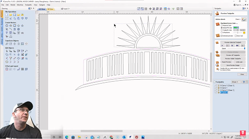
This design will have two main vectors – the bridge and the sun. We’ll go for an image of the sun peaking over the bridge, followed by a Welcome text right below.
Creating the Bridge
To start, set up your project and create a rectangle using the Draw Rectangle tool. Keep it centered using the Alignment tools. Then, you’ll need to create a row of smaller rectangles inside the bigger rectangles using the Array tool.
Then, draw another rectangle that overlaps with all the inner rectangles, making sure that it’s still inside the bigger rectangle. Remove some of the extra rectangles as preferred. In our case, we’ll remove some rectangles within to give a better image of a railing.
Here’s what it should look like:
Now, we’re going to put the inner rectangles together using the Weld Tool.
All you have to do is select all the inner rectangles and select the Weld tool under the Edit Objects menu. This will merge the rectangles, creating a comb-like vector.
Next, select all vectors and click on Distort Object. Tick the Bounding Box option, and Apply. Right-click on the upper line of the vector and turn it into an Arc. Drag to your desired level, and do the same for the bottom line of your vector.
We’ll also create a hillside where your bridge is perched on. We’ll do that by drawing a thin rectangle right below the bridge. Then, using Node Editing Mode, let’s turn both the upper and lower walls of the rectangle into an arc so it follows the bridge. We’ll also turn both ends into a Bezier Curve so that it gets curved.
After that, it should look like this:
Creating the Sun
Now that we have the bridge ready, it’s time to create our sun.
For our sun, we’ll be using the Draw Star tool and creating a star with 25 points. Drag that star in place and draw two circles at the center with the outer circle going a bit beyond the rays, creating an outline.
Then, using the Interactive Vector Trim tool, we’re going to remove all the unwanted vectors between the two circles and between every ray.
Then, we’re going to cut our sun in half by drawing a horizontal line at its center and deleting everything that you won’t need at the bottom. So you’ll end up with a half sun.
To make sure that the sun sits perfectly on top of the bridge, we’re going to ungroup the bridge vector and create an offset of the outermost outline. Then, we’re going to drag the sun down so it aligns with the offset. To finish off, we’re going to cut the excess vectors.
2.Adding the Texts
Now that the vector is ready, let’s add some text. For us, we’ll type in a simple “Welcome”, but for you, it can be anything under the sun. Literally!
To give our text some spice, we want to make the letter “W” and the last letter “E” a bit larger than the others and distort the letters in the middle.
Let’s start with distorting first. First, we’ll click on the Distort Object Tool and Insert a point in the upper left corner of the first “E” and another point in the upper right corner of the letter “M”. Right-click on the line between the two points you just created and turn that into an arc. Then you drag it down and adjust the positioning until it looks good.
To work on every letter independently, right-click on the text and Convert it to Curves. This way, you can ungroup the letters and work on each separately.
Now, you can enlarge the letter “W” and “E” to whatever size you prefer. You can also drag down a guideline to use as a reference and to keep both the same size. You can add as much text and vectors as you’d like. If not, the end product should look like this
Want to start a CNC wood carving business from home?
Download our 18-page guide packed with tips and advice from successful customers who have already made it happen.
Take the first step towards turning your passion into a profitable business!
3.Set Up the Toolpath
When you’re all good with your design, then we’re ready to VCarve our design. Our toolpath will have ⅛ of an inch Flat Depth and End Mill and a 60-degree Vbit. Then, we calculate and preview the toolpath.
You can play around with the toolpaths and vectors as much as you like (you can even add colors!) and when you’re satisfied, you can go ahead and run your CNC machine.
How to Make a Song Lyric Sign
Now let’s hop into something perfect for anniversaries, weddings, and family reunions — a Song Lyric Sign!
This design isn’t just meaningful, but it’s stylish and not to mention romantic. The best part? It’s easy and fun to create! Just follow these four simple steps, and your design should be ready in no time.
Connect with Digital Wood Carver
1.Add the Lyric Background
To start this design, we first need to create the lyric background. We want to create the illusion that it’s behind the text (or vectors) we’ll design later so it needs to be set up in place.
For this project, we’ll be using an 11 ¼-inch by 22-inch board. Then, type in any song lyric that you want on the Create Text Tool and center it on the board using the Alignment tools. For us, we’ll work on the lyrics of Amazing Grace by John Newton with the typeface Monotype Corsiva.
2.Add the Front Text
After creating your background text, it’s time to lay over your preferred text. If you want, you can even challenge yourself with traced vectors instead. But for practice, some laid-over text looks just as nice.
Going with the text-over-text design, we want the title “Amazing Grace” over the lyrics. We’ll use the typeface Times New Roman to emphasize it better and we’ll set it right in the middle of the board with the alignment tools.
3.Clear Unwanted Vectors
To achieve that illusion where the title sits in front of the lyrics, we need to clear the vectors inside the words “Amazing Grace”. Hence, we’ll do the same process as we did in the Vectric Tutorial Part 1 with the eagle and shield with slight adjustments.
Offset the text outwards to 1/16-inch and tick the Select New box. This way, the offset boundary is automatically selected. Select the background text followed by the boundary, then Clear Inside Boundary using the Trim Objects tool.
Note: Always select what you want to trim first before selecting the boundary you want to trim to.
After clearing the vectors, you can now delete the offset created earlier to leave a space between your front and background texts.
4.Set Up the Toolpath
Now that you have the design, you’re ready to set up your toolpaths.
Using the VCarve Toolpath, we won’t use a Flat Depth or a Clearance Tool for this project. Instead, we’ll just use a 90-degree Vbit. Calculate and preview the toolpath and when satisfied, then you’re good to go!
Here’s the final product of our Amazing Grace song lyric sign:
And that sums it up! Hopefully, this guide has given you a better idea on how the whole design process works and how to use Vectric Aspire.
Sign designing has never been this easy! These are just two out of five designs featured in Laney’s tutorial video. If you want to learn the rest, check out Let’s Carve a VCarve Sign Tutorial Video Part 1 and Part 2.
---
Don’t miss out on bi-weekly live tutorials on SpindleTV where you can follow along and ask questions as Laney takes you through all kinds of designs.
Browse CNCs
From hobbyist to commercial and everything in-between.
Let’s Design a VCarve Sign – Sign Designing Tips Part 1
In this tutorial, we'll create a VCarve sign using Vectric Aspire tools. Custom signs can be placed anywhere and add aesthetic value to various spaces! This design is suitable for beginners and intermediate carvers and can be used with Vectric VCarve Desktop and VCarve Pro software. It can also sell well on platforms like Facebook Marketplace and Etsy.
Custom signs can be put up anywhere – in your living room, by your door, right outside your office, and the list goes on. Wherever it is, signs add aesthetic value to all sorts of spaces and the right custom sign can sell like hotcakes on Facebook Marketplace and Etsy!
So in this tutorial, we are going to be designing a VCarve sign using the different tools available on Vectric Aspire. Best for beginners and intermediate-level carvers, this design is also compatible with both Vectric VCarve Desktop and Vcarve Pro design software.
Follow through the entire process with Laney Shaughnessey on SpindleTV and don’t forget to hit the SUBSCRIBE button to keep up with our bi-weekly LIVE Vectric classes!
Special Calculation Characters
Before we start, let us introduce you to special calculation characters. Special calculation characters are shortcuts that you can use in equation boxes. To give you an idea, the letter ‘w’ is a special calculation character for width.
These characters help in conversion and make it easier for you to input the right value without having to type it in manually. For instance, if you want to set your point at the center of your profile, you can type down “w/2=” and it will automatically substitute ‘w’ with your exact width measurement and divide it by 2.
To find a complete list of these symbols, you can click Help Contents under the Help tab, then select the Calculate Edit Boxes under the Interface menu.
Now that you have a reference list you can use for your calculations, we can start designing our VCarve sign!
1.Creating a Round-Edged Border
Like any other projects, let’s start by completing the Job Setup.
For our sign, we’ll be working on a 16x11-inch, single-sided project, that’s 3 ¼ inches thick. The Z Zero Position will be set on the Material Surface, and the XY Datum starts at the bottom left corner.
The base of this sign will be a round-cornered rectangle, so we’ll be using the Draw Rectangle tool and tick the Radiused External box. Then, set it to your preferred Radius (which for us is 3 inches).
As for the size, we want the rectangle to be an inch away from the boundaries, so we’ll subtract 1 from the width and height of the entire project to get the exact size.
Lastly for the base, we’ll create a ½ inch border using the Offset Inwards tool.
2.Tracing an Image
Now, let’s learn how to trace some images.
Import your image and click on Trace Bitmap Tool. Turn off Bitmap fading and drag the Threshold to a 0.75 and click Apply. Then, turn off the Bitmap layer and you should be left with a traced vector of your image.
If your image is low quality and is leaving bumpy curves, you can increase the Noise Filter to smooth out these lines. But if not, then it’s best to keep it at 1 Pixel.
Pro Tip: Only trace images ONCE.
As soon as you have a traced vector, create a new 6x6-inch project and paste the vector. Center it onto the board, and save it on your Custom Images folder. Your Custom Images folder should be created inside the Clipart folder which you can find when you follow this path:
Local Disc (C:) > Users > Public > Public Documents > Vectric Files > Clipart > Custom Images
This way, you can easily find your traced images in your software’s Clipart tab. For your convenience, you can also create a desktop shortcut for this folder so you won’t have to travel so far when saving a new traced image.
3. Adding, Editing, and Aligning New Vectors
This sign will have four main components – the eagle, the shield, the banner, and the stars. Since we already have a traced image of the eagle, you can easily import and set it at the center of your project.
Creating the Custom Patriotic Shield
For the shield, we’ll create it from scratch using Shield 5 under 2D Vectors in the Clipart Tab.
Using Node Editing, we’ll drag the points and create arcs on the right side to create the shape we want our shield to have. Then, we’ll cut the vector in the middle, delete the left side, and create a mirrored copy to the left. Then, we’ll use the Join Vectors Tool to group the vectors together, and we will have a new shield shape.
Then, we’ll also use the Draw Rectangle tool to add the shield design. We’ll also add a line at the center which we can use to mirror certain vectors.
For example, if we want to mirror a rectangle so that it’s perfectly symmetrical on the other side, we’ll just select the rectangle and the center line, go to the Mirror tool and click Flip About Line.
Then, we’ll offset the shield outward to add a border and trim the extra vectors using the Interactive Trim Tool. As a final touch, we’ll add three stars at the top of our shield, with the center star a bit bigger than the rest.
Group it as one item, and the final shield will look like this:
Adding One Vector on Top of the Other
Now for this design, we want to create the illusion that the eagle is in front of the shield and the banner is in front of the eagle.
To create this illusion, the first step is to drag each vector to its rightful position. Then, we need to ungroup the eagle and create two extra outlines around the eagle so that it carves correctly. To do this, we have to offset it outwards by 1/16 inch twice.
Select the shield and the outermost boundary of the eagle you just created, and Clear Inside Boundary using the Trim tool. Then, delete the outermost boundary and regroup the eagle.
Adding and Aligning Star Background
For the background, we want to add a few stars around. Duplicate the star on the shield and create three copies of the star on the left side of your project.
To align them perfectly, select the three stars, hold the Shift key and select the inner boundary of your rectangle. Then, under Alignment tools tick the Inside Last Vector box under Space Selection, space it vertically, and click on the left to right Align to Selection.
If you want to edit the placement of your stars, you can just select one and bump it to whichever direction you want using the arrow keys on your keyboard. When finished, reselect the three stars, go to the Mirror tool, tick Flip About Job Center, and Flip Horizontally.
Following the earlier process of moving a vector in front of the other, the final design with the banner should look like this.
Want to start a CNC wood carving business from home?
Download our 18-page guide packed with tips and advice from successful customers who have already made it happen.
Take the first step towards turning your passion into a profitable business!
4.Adding Texts
Let’s add some texts!
For this design, we’ll type in “America” at the top part, and use the Alignment tool to center it onto the material. We’ll also use the Edit Text Spacing and Curve tool to add a bit of an arc to our text.
Feel free to play around with the typeface and font styles!
5.Calculate the Toolpaths
When you’re finished with your design, then we can proceed to calculating the toolpath.
Open Toolpaths and make sure all of the details are correctly typed in. Start Depth should be at zero, Flat depth at ⅛ inch, End Mill at ⅛ inch, and Raster Cut. Then, select the entire design except for the outermost border and Calculate.
You’ll have another toolpath just for the outermost border since this will cut off the entire edges and leave the round-cornered base.
Preview the Toolpaths and if you’re satisfied, get your CNC machine running!
Connect with Digital Wood Carver
When you’re finished with your design, then we can proceed to calculating the toolpath.
Open Toolpaths and make sure all of the details are correctly typed in. Start Depth should be at zero, Flat depth at ⅛ inch, End Mill at ⅛ inch, and Raster Cut. Then, select the entire design except for the outermost border and Calculate.
You’ll have another toolpath just for the outermost border since this will cut off the entire edges and leave the round-cornered base.
Preview the Toolpaths and if you’re satisfied, get your CNC machine running!
–
To follow through the entire step-by-step process, watch the first part of Laney’s Lets Design a VCarve Sign Tutorial on SpindleTV! Don’t forget to like and Subscribe to the SpindleTV channel to keep up with the latest updates and to join our LIVE Vectric classes every other week.
Browse CNCs
From hobbyist to commercial and everything in-between.
How to Create a Maltese Cross – A Simple Approach to Design and Layout
Looking for a new CNC project? Get your hands busy this weekend and create your very own Maltese Cross! We’ll be creating a Maltese Cross vector using guide lines and shape tools in Vectric Aspire. As soon as you get the hang of the entire design process, we’ll take the tutorial up a notch and create a 3D Maltese Cross model.
Looking for a new CNC project? Get your hands busy this weekend and create your very own Maltese Cross!
In this tutorial, we’ll be creating a Maltese Cross vector using guide lines and shape tools in Vectric Aspire. As soon as you get the hang of the entire design process, we’ll take the tutorial up a notch and create a 3D Maltese Cross model.
For a more detailed tutorial, follow the entire process with Laney Shaughnessey on SpindleTV!
Hit the Subscribe button so you won’t miss our bi-weekly LIVE Vectric classes!
Creating the Project Guide Lines
A Maltese Cross is a symbol of safety and security used by firefighters. It’s characterized by symmetrical shapes, and you’ll notice that its design differs from one department to the other.
Its perfect balance of aesthetics and meaning is exactly why it’s one of the best projects you could practice or experiment on.
Since a Maltese Cross is perfectly symmetrical, using guide lines makes it ten times easier to create the vector. These guide lines can be dragged out from the rulers at the top and left side of your workspace. You can also adjust the angle and position of every guide line by right-clicking on it.
Additionally, you can also add parallel guide lines if you need more than one in a row. You also have the option to lock the guide line to avoid accidentally dragging it out of place, or delete the guide altogether.
Creating the Maltese Cross Vectors
Job Setup
To start, complete the job setup by filling in the necessary details. For this project, we’ll be doing a single-sided job on a 12x12-inch piece. The Z-zero position will be at the bottom of the material and the XY Datum is set on the bottom left corner.
Feel free to alter any of these as needed!
Drawing the Layout
Now that you have your job setup, we can now create the layout of our Maltese Cross. Since the project is perfectly symmetrical we’ll be drawing the layout using guide lines to keep it proportional.
First, use the Draw Rectangle tool and create a 7x7 inch square which will serve as your base. Then you’ll need to create three overlapping squares at every corner of your base. These squares will make it easier for you to drag and position your guide lines on your project.
For their sizes, every square should be twice larger than the previous one:
First Square: ⅜ inch square to the bottom left corner
Second Square: ¾ inch square to the same corner
Third Square: 1 ½ inch square to the same corner
The squares should look like this:
Next, you’ll need to mirror the squares so you’ll have it at all four corners of your project. To do so, select the three squares and click on the Mirror tool on the menu. Tick the options Flip about Job Center and Create a Mirrored Copy and flip horizontally, vertically, then horizontally again.
Now you should have your square guides at every corner of your project.
At this point, you’ll now need to match the guide lines to all sides of your project. For a complete and detailed run-through of every guide line you’ll need, take a look at Laney’s Tutorial Video on SpindleTV.
Adding Curves
With guide lines in place, it should be a breeze to create the straight lines you’ll need for your Maltese Cross layout. But what about the curved parts?
To add a curved shape, go to Node Editing, tap the intersection on the third square guide line, and Insert a Point. Zoom in to make sure that the point is exactly on the intersection. Do this for all four intersections in the same line as seen on the image below.
Then, right click the line between the two inner points and turn it into an Arc. Then, pull the arc on the outermost wall of your base.
Now, you don’t want your cross’ edges to be too sharp. So click on the Create Fillet, type in a 1/16 inch radius, and click on the edges you want to be rounded.
Next, with Node Editing right click the short line inside your 1 ½ inch square and turn the line into a Bezier. You’ll now have two new points which you can use as an anchor to drag and create your curves. Ideally, the anchors should be placed perfectly diagonal to the line.
If you want them perfectly aligned, select the anchor you want to align with, hold the shift key, select the anchor you want to adjust, hit X and voila! The two anchors should now be perfectly symmetrical. Repeat the process for all the curves for this section.
Duplicate the Shape
After finishing the first wing of your cross, then you can now delete your square guide lines and duplicate the shape for all sides. But before you do that, offset your shape outwards to ⅛ inch, and tick Create Sharp Corners If Any.
Then , under Offset and Layout, select Circular Copy and set the center of your material as the Rotation Center. Type in the number of copies you want (for this we need four) and set the total angle at 360 degrees.
Click Copy and you should now have four wings on your project.
Clean Up Your Vector
Now that you have your wings, then it’s time to clean up your vector.
First, you’ll have to offset your circle inwards to ¼ inch, no sharp corners. Then, select all four inner triangles on your wings and your outer circle (the outer circle should be selected last as this will be your boundary), and click on the Trim tool and select Clear Inside Boundary.
For the outer triangles, we’ll be using the Scissor tool to remove the smaller unwanted vectors. As soon as you have an outside boundary and some inner shapes, then you can now select and delete the lines left inside the circle.
The end layout should look like the image below. To know which lines to remove, take a quick look at Laney’s tutorial video.
Add Texts and Symbols
Now you’re ready to add some symbols and text.
To make sure that the placement of your icons and texts are proportional, you can offset the inner circle outwards depending on how far from the circle you want them to be. In this case, we’ll be offsetting it outwards by 1.22 inches.
Using the scissor tools, remove the unnecessary vectors between the wings so that the guide is kept inside every wing.
Then, add and select your desired text, hold your Shift key and select the curved vector you created as a guide. Click on the Text Around Curve tool and adjust the properties.
Here, we’ll be selecting On Curve, Middle, Align to Curve, and Text on the Other Side. You can also scale the size and spacing however you want. Repeat the process for the other text.
For the symbols, you can simply open up the .dxf files and drag each of them to your desired position. Clear up your text guide lines and then you have your design ready for modeling!
3D Modeling a Maltese Cross
Now that you have your design ready, then it’s time to proceed to CNC modeling. The process is more or less similar with other projects, but of course, you may customize it however you prefer.
You have two ways to work on the text and icons. You can have it VCarved in or raised for simplicity and speed, or you can model them individually. In this section, we’ll be going over Modeling via Vectric Aspire. But if you want to do a simple VCarve you can take a look at how Laney does it in his tutorial.
Create the Foundation or Base
Let’s start by creating the base. Under Modeling Tools, select Create Shape and set the material to a Flat Surface with a ¼ inch base height.
Since we want pockets around the perimeter, let’s create a new component and select the inner vectors (not the text and icons!). Then, we set the shape to a Curved Profile with the preferred angle and base height. For us, we’ll be doing a 45 degree angle at a ¼ inch base height.
2. Model the Text and Icons
For the text, we want it slightly above the pockets with a curved top. So let’s create a new component and set the texts as a curved profile with a 35 degree angle and a base height of ¼ inch.
The same thing goes for the icons. Since we don’t want it to be too puffy, we’re going to set it at a 25 degree angle while keeping the ¼ inch base heights. However, you’re always free to change this into a Flat Profile and adjust the base height however you prefer.
3.Add Drafts to Your Model
As a final touch up, let’s add a draft to the entire model. The drafts will remove the sharp edges to the model and add a nice angle to it.
Select the Add a Draft to the Model tool and set the angle. You can experiment on this one, but for us we found the best angle to be at 15 degrees. To keep the model clean, you can also turn off the visibility of the components.
You can also use the Smoothing Tool as a final touch, and you’re done! You now have successfully created your 3D modeled Maltese Cross and 2D vector on Vectric Aspire.
For a more detailed run-through process, watch Laney’s How to create a Maltese Cross tutorial on SpindleTV. Also, feel free to join us on our bi-weekly LIVE tutorials on SpindleTV where you can follow along with Laney and ask questions along the way.
Shop CNC Routers for Hobbyist, Professional and Commercial use!
Buy a CNC
From hobbyist to commercial and everything in-between.
Creating a Stacked Text Design to Enhance your CNC Projects
Put text on top of other text in your projects to elevate your abilities to produce amazing projects.
Creating a Stacked Text Design
Every Stacked Text or commonly known as Text-On-Text Design starts out the same way, by creating the different layers for the design.
Original Layer
Top Text Layer
Bottom Text Layer
Welded Text Layer
Lower Third Layer (Optional)
An optional layer can be created called the Lower Third Layer for any items outside of the Stacked text… Here is an example of lower third text in “Pink”
Once the Design is completely laid out in the original layer, you will begin to copy the different parts of the design into the appropriate layers.
In the example shown above. The first names, Jonathan & Rachel will be copied into the “Top Text Layer”, The Last name Parsons will be copied into the “Bottom Text Layer”, and the text We decided on forever, February 16, 2022, will be copied into the “Lower Third Layer”.
Now let’s discuss the Border Vector. All Stacked text designs will have a border vector, this is what makes this type of carving work. Creating a boundary that the carving will be restricted within. Causing the carving to remove all material between the border and the design. Leaving the design raised. So, with such an important role, we need to make sure the border is copied to the correct layers.
Select the border and copy it to the “Top Text Layer” and the “Welded Text Layer”.
With these steps complete, you should have layers that look like the images below. This is the first phase, there are still additional steps to take before we are ready to toolpath the design.
Figure 1 Top Text Layer
Figure 2 Bottom Text Layer
Figure 3 Welded Text Layer
Figure 4 Lower Third Layer
Now that we have verified that we have copied the design elements to their appropriate layers, now we begin to prepare for tool pathing.
Step 1. Determine how tall you would like each layer of the stacked text to stand. In this example we will use my preferred height of 0.125” for the Top Text and 0.125” for the Bottom Text for a total depth of pocket of 0.25”.
Step 2. Now that we know our desired text height, we need to determine our offsets. This will be based on 2 factors, the angle of the Vbit we are using and the height of our text. In this example we will be using a 60 Degree VBit. Let’s look at the layout to determine our offset which is 0.0722
Figure 5 Offset
Now we can use this known offset for our Top Text and our Boundary Lets start by working in the Top Text Layer and cleaning up our text. Our text happens to be a script font, so there are overlapping lines in the text that need to be removed by welding the text together. See the figure below.
Figure 6 Welded Top Text
Once the top text overlapping lines have been welded together, we can now copy the Top text over to the “Welded Text Layer”. Before we leave the “Top Text Layer” we need to Offset the border INWARD by the offset amount of 0.0722 deleting the original border on the “Top Text Layer”
Figure 7 Offset Border inward on Top Text Layer
We can now move to the Welded Text Layer to Offset the text we copied onto the layer earlier. We will offset the text outward by the offset amount of 0.0722.
Figure 8 Offset Top Text outward inside Welded Text Layer
once offset we will group the offset vectors together.
Now we can move to the “Bottom Text Layer”.
In the “Bottom Text Layer”, we simply need to copy the bottom text to the “Welded Text Layer” once copied over, we need to group the bottom text vectors together. If this text had still been a font, we would have needed to convert it to curves first, then group it together. In this case, the text was already vectorized during the formatting of it to give it the unique arc shape.
This will give us two grouped objects, the bottom text, and the top text. Select both groups and weld them together using the weld tool.
Figure 9 Welded Top and Bottom Text on Welded Text Layer
Now that the Top and bottom text are grouped, we are very close to being ready to create the toolpaths, but first we must deal with the “Lower Third Layer” because we need to protect the area where this lower third will be from being milled away.
On the “Lower Third Layer” select all of the text and create an offset the is 0.125”
Be sure to have the option for “Select New” checked, this will make it easier for making the second offset, this time make it for 0.15”, this will give you a double boundary around the Lower Third Text. NOTE: if there were any other objects, such as models, flourishes, or other elements, you would create offsets around them as well using the same distances above. DELETE all little misc. vectors that were created during this process only keeping the main vectors surrounding the words.
Figure 10 Offset Boundaries of the Lower Third Objects
Now, the inner Offset needs to be copied to both the “Top Text Layer” and the “Welded Text Layer”
Now we are ready for Tool Pathing. Start by turning on the lightbulbs for the “Top Text Layer”, “Welded Text Layer” and “Lower Third Layer”
Next Switch to the CAM side of the software to the Toolpath Operations.
Create a VCarve Toolpath with a 0.00 Start Depth and a 0.125 Flat Depth. Choose a 60 Degree 0.25 VBit for the main tool, and I have opted for a 0.25 Endmill and a 0.125 Endmill for the Flat area clearance tools. NOTE: both tools are not necessary, but by using both, I will get cleaner results around the letters.
Be sure to choose Raster for the Machining Strategy, in the Tool Specific options.
Figure 11 Top Text Toolpath
In the Vector Selection section, click on and open the Selector
Figure 12 Vector Selection Options
Check off the boxes for open and closed vectors, then check off the box to associate with toolpath and from the list on the right, check off ONLY the Top Text Layer. We are associating the “Top Text Layer” and all the vectors on that layer with this toolpath. Click close to close the window and name the toolpath Top Text, then calculate the toolpath.
Figure 13 Top Text calculated toolpath result
Your Preview should look like the image above.
Next Open a New VCarve Toolpath. This time we want a Start Depth of 0.125 and a Flat Depth of 0.125 with the same tools we used for the Top Text Toolpath.
All the settings should be the same, so go down to the vector selection section and open the selector window. This time uncheck the Top Text layer and check the Welded Text Layer. Be sure that associate with toolpath as also selected over on the left side.
Figure 14 Bottom Text Vector Selector Options
Click Close then calculate the Toolpath
Figure 15 Bottom Text Toolpath calculation results
Your preview simulation should look like this at this point.
We are now in the home stretch, only a few more things to do to complete this design.
Now turn off the lightbulbs for the top and bottom text layers leaving only the “Lower Third Layer” visible. Select the inner boundary offset vectors around the Lower Third Objects
Figure 16 Lower Third Pocket Vectors Selection
Create a pocket toolpath with a start depth of 0.00 and a cut depth of 0.125 using a 0.25 Endmill as shown.
And then for the final toolpath, Select the outer Offset Boundary vectors and The Lower third Text or objects and create a VCarve toolpath with a Start Depth of 0.125 and a Flat Depth of 0.125 using the same 60 Degree VBit and 0.125 Endmill. Remove the 0.25 Endmill from the clearance tool list, we will not be using it for this toolpath. Calculate the toolpath.
Preview the results
Figure 17 Final Results of the toolpaths.
Now rearrange the toolpath in your list so that the 0.25 Endmill toolpaths are together, and the 0.125 Endmill toolpaths are together, and the 60 Degree VBit Toolpaths are together. Make sure they are ordered with the Top Text Toolpath first for each section. I have renamed the Toolpaths to include the bit type and size in the name as shown.
For saving the toolpaths, we have chosen the option to save all visible toolpaths to multiple files, and we have the option to Group where possible is checked, this will group all toolpaths using the same bit together into 1 toolpath.
Check all the toolpaths to make them visible. Then save them giving the file a unique name, the software will do the rest by adding the appropriate name to the toolpath.
Be sure to save your design if you have not done so already. Saving the Toolpaths and Saving the Design are 2 separate steps.
This completes this project!
How to Design a Wavy 3D US Flag in Vectric in 4 Steps
Want to make a 3D wavy American Flag with your CNC? Here’s an easy 4-step process on how to create a rippling 3D US Flag model using Vectric design software.
Want to make a 3D wavy American Flag with your CNC?
Here’s an easy 4-step process on how to create a 3D US Flag model. This tutorial uses Vectric Aspire design software.
Follow along with this video for a detailed walkthrough of the project! Follow Laney Shaughnessey on SpindleTV for Vectric tutorials and live weekly classes.
Download Project Files:
Vector Files (.svg and .dxf) of 2 PERFECTLY Proportioned Flags (Current constitutional Flag and 1776 Betsy Ross Flag) The flag vectors are scalable (Keep the aspect ratio) and will give you a good head start without having to create the vectors from scratch.
1. Set Up Your Work Area for your 3D Flag
Start by completing your Job Setup. Depending on your project and material, fill in the job type, size, Z Zero Position and so on. You can use the machine bed for the Z Zero Position, and the center or any of the four corners of your material for the XY Datum Position.
In this case, we'll be working on a single-sided model with a 24 1/4-inch-long, 15-inch-wide, and 3/4 inch-thick board. Since we’re creating a 3D model, the Resolution should be set at Maximum for the best results.
At times, you may only see the first three options available – Standard, High, and Very High. To gain access to higher resolutions, simply hold the Shift key as you click on Create a New File.
2. Design the Components of your US Flag Carving
Next, it’s time to add the components.
There are three main components in a 3D US Flag – the flag base, the stars, and the stripes. Any additions such as text, emblems, and ripples are optional, but we’re going to teach you how to add those later on.
Want to start a CNC wood carving business from home?
Download our 18-page guide packed with tips and advice from successful customers who have already made it happen.
Take the first step towards turning your passion into a profitable business!
Create Your Stars
On the Create Vector section at the left, select the most appropriate tool. In this case, we’ll select the Draw Star Tool. Type in the number of points your star should have, the inner radius percentage, and the outer radius percentage.
Then, click Create and your first star should appear on your page.
Click on the star and check whether the dimensions match your preference and modify as you see fit. Just make sure to tick the Link XY checkbox to keep it proportional.
Next, duplicate your star using the Array Copy tool under the Offset and Layout section.
For the flag, you’ll need 9 rows and 6 columns of stars and each should be one seat apart from the next, but right below the row above it.
To do so, type in your star’s size on the X under Gap on the left and type in a negative on the Y (e.g 0.0948). The Row/Column Displacement should also be the same as the star’s size to keep them aligned.
Click on Copy and you should now have a star field. Don’t forget to delete the excess stars!
Connect with Digital Wood Carver
After that, you can now create the rectangular border and the stripes using the Draw Rectangle tool under Create Vector.
Repeat the whole process and adjust as needed using the Alignment Tools available.
For a step-by-step process on how to create each component, you can check out Laney’s Tutorial Video.
How to Add Ripples in your 3D Flag
If you want a ripple effect on your flag, then there are two ways to proceed – choose among existing wave options or create one from scratch.
To view the existing ripple wave options, you can click on the drop-down list beside 3D View and see if anything fits your taste.
If none of them does the trick, then you can opt to do it manually. Select the Line tool and draw the rails and the curve. Edit the nodes if needed, and go back to the Two Rail Sweep tool. Select the two rails, and click on Use Selection under Drive Rails. Then, select the drawn ripple wave and click on Apply.
Now you have a manually designed ripple and can view the project in 3D view. Edit as much as you need until you’re satisfied!
How to Add Text to your 3D Flag
If you want to add text into your project, select the Create Text tool on the Drawing Section and type in the word or phrase you want added.
Pick a typeface, adjust the size, and drag the text on the desired position.
Then, add a border using the Create Fillet tool and pull the nodes as close to the text as possible. Then, clear excess vectors inside the boundary and model the text.
How to Add Emblems to your Wooden Flag
Another component you can add are emblems or seals. A common issue that you may encounter while attaching your seal is that the stripes cut through it too like the image below – which we don’t want.
To fix this, click on the Trim tool under the Edit Objects section. Then, click on the outline of your seal and select Clear Inside Boundary to clear up the vectors within the outline.
After this, you can adjust the gaps once more and model your seal without the stripes cutting through!
3. Model the Flag’s Components
After designing the components, it’s time to begin modeling.
Start off by drawing a rectangle over the entire project. Then, on the Modeling menu, click on Create Shape and set a base height depending on the thickness of your material.
At this stage, you can choose between a curved, prism, or flat profile but we’ll stick to a flat profile for now.
As soon as the base is done, you can now add more components using the same method.
For the stars, just drag and select the stars, create shape, and type in your desired base height.
You can also decide how you want one component to be combined with others. You can have them protruded or recessed.
Next, you’ll want to add a Draft to all of your components to give the walls more angle and smooth out edges.
To do so, you’ll just have to select all components, select Add Draft under Modeling Tools, set it to around 30 degrees and apply.
Make sure to monitor your project using the 3D View to make sure you’re getting what you want!
4. Preview the Tool Path for your 3D Flag Carving
If you’ve already created all the desired components, then you can now create the Toolpath for the model.
Click on the Toolpath button beside Model on the upper left corner and select 3D Model Cut. If possible, create a rough cut beforehand.
Then, check your Material Setup and make sure nothing is out of proportion. Make sure to leave a bit of space around the boundary using the Offset tool.
After the calculation is done, you can now Preview the Toolpath and get your machine running!
And that sums it up! Hopefully, this guide has given you a better idea on how the whole design process works and how to use Vectric Aspire.
For a more detailed run-through of the process, you can watch Laney’s 3D US Flag Model on his SpindleTV YouTube channel.
---
Don’t miss out on bi-weekly live tutorials on SpindleTV where you can follow along and ask questions as Laney takes you through all kinds of designs.
Browse CNCs
From hobbyist to commercial and everything in-between.
Retired Sheriff Launches Successful CNC Business with ZERO Experience
See how Mike scaled up his woodworking business with a commercial DWC5100 CNC Router and a laser… with ZERO experience with CNCs!
When Mike Bowlby retired from the Sheriff’s Department, like most retirees do, he and his wife started looking for meaningful ways to keep busy – preferably one that was highly-rewarding, but without the stresses and obligations of a regular job.
They found what they were looking for by starting a CNC woodworking small business with the help of Digital Wood Carver.
Their journey started with a single DWC2440 CNC Router.
Mike began with carving police badges, and by now he’s sold hundreds of them in the United States and even some overseas!
His wife makes all kinds of signs and jewelry as well.
As the demand for larger projects increased, they’ve now fully transitioned to a DWC5100 commercial CNC, plus a 90 Watt Laser - both from Digital Wood Carver.
Here’s a walk through the Bowlby’s CNC success story, told by none other than the man himself.
How it Started
“My wife Krista and I started to make things from wood after I retired from the sheriff's department. We started a small business and started our carving with a Digital Wood Carver DWC2440.
“A friend of mine I went to the FBI National Academy with had one and recommended them. He said the customer service is better than anything I've ever seen in my life and he's absolutely right.”
“I like to carve police badges and I sell them. I've sold some just not only in the United States but outside the United States.
“We started off doing that until someone asked us to carve a 30 inch batch. So we couldn't carve a 30 inch badge based on the size of the machine we had, so we talked about it.
“We got a text kind of a broadcast from Laney, and they had one DWC5100 that they were going to sell before the price increase. We contacted Burl and asked him to hold it for us and drove down to Martinsville.
“Talked to Burl about it and what the differences were, the pluses, the minuses. We reorganized a little bit and they delivered it in August.
“So now we can now not only cut the small badges that we once did but we can cut something as wide as 50 inches and as long as 100.”
The DWC5100 Machine and 90-Watt Laser Quality
“I seldom have any trouble with it.”
“The 220 volt, water-cooled spindle is much quieter than the router was and you can actually stand nearby and have a conversation while the spindle's running. The size of the table obviously was another factor, and just the sheer size and the weight of it and how well it's put together.
“The good thing about it too, different from a router, not only are the feed rates but the speed rates of the router bit itself they're adjustable so you can vary the speed and feed rates which makes up the whole cutting process suit your project.
“The VCarve Software makes it so easy for the average person to use. It takes a lot of the guesswork out of it.
“the laser does a lot of different things than the CNC does because it can do finer detail on smaller things”
“In January we bought a 90-Watt cabinet laser. My wife's wanted one for some time and she started working with it and it's just about running 24/7 ever since!
“Krista's getting ready to cut some leather with our machine. She's also used her laser on canvas bags, cloth bags, cotton bags, acrylic…”
“It's helped us expand our business, and it's helped us meet new people.”
Starting with Zero CNC Experience
“I knew the concept [of CNC] but I knew nothing about programming. I knew nothing about how to make it run. I knew nothing about designing...”
“This whole CNC process is not very straightforward. It's complicated, but it can be learned. I learn a lot from videos, I learn a lot from other people who have experience.
“With Laney's expertise and knowledge, passing that along in little bits so that I could absorb it and be able to retain it. Then I've learned enough that I can do a lot of things.
“You can't take everybody's word as a gospel, you have to kind of make your own decisions based on what you know and the capabilities of the machine. But I have confidence in this machine that it'll do just about anything I want to do”
Why Digital Wood Carver?
“The fact that they're there anytime you call them for anything”
“I've talked to [Laney] enough that I can send him a text message and explain to him the problems I'm having problems with and he'll either send me back an answer or he'll call me within a few minutes.
“The customer service is outstanding. The company itself is outstanding, and I've met several of the guys that work there and they're all good people and they would stop to do anything they can to help you.”
And that’s a wrap!
We are extending our sincerest gratitude to the Bowlby family for sharing their inspiring CNC success story. It is our pleasure to be part of this journey and as always, we hope for nothing but better days ahead for you, your family, and your CNC business!
To learn more about Bowlbywood Creations and their wondrous custom-made products, you can visit their official website and Facebook Page.
Offer CNC Education at Your School with Digital Wood Carver
Looking for ways to improve your school’s CNC learning? Unlock your school’s full potential with Digital Wood Carver.
Looking for ways to improve your school’s CNC learning? Unlock your school’s full potential with Digital Wood Carver.
Better Resources to Improve CNC Learning Experience
CNC machining is an in-demand skill in various industries – woodworking, metalworking, engineering, you name it.
With better knowledge and exposure to this field, students gain an upper hand in many STEM programs, and are equipped with excellent problem solving skills and creativity.
Many schools all over the world have taken the leap to develop their own CNC program. However, only a few of them can truly excel due to the lack of hands-on exposure.
Fortunately, Digital Wood Carver offers a solution to this problem. Providing the right equipment and support, we can help you carve beyond textbook learning in just a few steps.
Affordable and Highly Durable CNC Machines
With Digital Wood Carver, educators can easily incorporate high-quality machines in CNC lessons and bridge the gap between traditional and modern woodworking.
From smaller benchtop models to large format CNCs, we make it easy for you to get a cost-effective and durable machine that will best fit your program.
Our beginner-friendly DWC1824 Mini Carver is everything you need to get started, with full packages under $3,000. So no more worries about going over the budget or risking student’s safety!
For maximum flexibility and project capacity, Digital Wood Carver’s flagship CNC, the DWC2440 is the ideal model for educational programs.
Sturdy and durable, the DWC2440 is a production-level CNC that has many options and add-ons to enhance projects even further.
Teach - don’t waste time maintaining and repairing
Our experience with many schools is that they often opt for the cheapest bid, and this can result in classrooms trying to learn on substandard machinery that they often spend more time fixing than using.
For a successful CNC program that students can get excited about, you need a reliable CNC that you can count on.
Get Help from Experts
Digital Wood Carver can also assist in training and offer support for your instructors and classes.
Live CNC tutorials can be broadcasted as special classes.

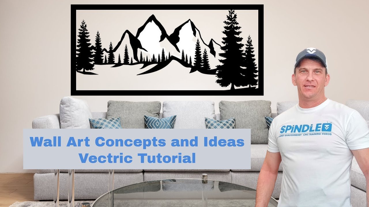
All you have to do is arrange a call, and our knowledgeable staff will happily walk the learners through machine operation step-by-step.
Learn Anytime, Anywhere
Last but definitely not least, schools can also enjoy massive online support from the Digital Wood Carver community.
Educators and students can access more than 100 in-depth training videos on the Digital Wood Carver Youtube channel and SpindleTV YouTube Channels and instructors can join the Facebook Owners Group where CNC owners share tips, post recent projects, and help out newbies get started on their CNC journey.
The opportunities are endless!
Optimizing CNC Education, One School at a Time
Currently, Digital Wood Carver works with 48 educational programs and correctional institutions all across the country. And you can easily become one of them.
It’s about time we let the kids expand past 3D Printers and let them explore the versatility of CNC machines. This way, schools can modernize their CNC programs, equip their students with exemplary CNC skill sets, and keep up with the rising demand in the industry.
For more information, feel free to contact us and we’ll happily respond to your questions and concerns, and help you create an amazing CNC program.
Level Up Your Sign Making Business with the SmartBench Large Format CNC!
Add a large-format CNC to your shop for less than $10,000 and cut signs from multiple materials like wood, B-board, corrugated plastic, etc as well as use for plotting or as a vinyl cutter!
Add a large-format CNC to your shop for less than $10,000 and cut signs from multiple materials like wood, B-board, corrugated plastic, etc as well as use for plotting or as a vinyl cutter!
No CNC? You’re Missing Out!
Producing large signage is challenging for any small sign-making business. The lack of space and machinery limits you to smaller project sizes, restricting your ability to support your customers.
This problem can be solved with a large-format CNC router that is easily collapsible and affordable… CNCs are a versatile addition to your sign-making arsenal, multiplying the ways you can provide value for your customers.
When used together with existing resources such as vinyl cutters and printers, a large format CNC allows you to cut out large signs quicker and more efficiently, and provide more value-added services in addition to more basic signage requests.
CNC routers can cut through a wide array of materials like foam core, corrugated foam, plywood, plastics, acrylics, ACM, vinyl and so much more.
Cutting acrylic
So you’ll be able to achieve higher-quality products without the need for extra hands and all-nighters doing it with a table saw and jigsaw or outsourcing!
The CNC Learning Curve
Integrating a CNC router is pretty simple for most sign makers because the production process is very similar to what you’re already used to.
Visual display makes it easier to get projects running
Once you have your 3D or vector-based design, all you need to do is load it onto a USB and plug it into your CNC, and input some basic CNC-specific information (bit size, depth, cutting speed, etc.). Then, you can set up your material on the machine, load the project, and let it run!
SmartBench Precision Pro – The Best CNC Router for Sign Making
Precise cutting of a variety of materials including acrylic, plywood and signboard.
The SmartBench Precision Pro is the perfect sign-making CNC for small businesses that want to dream big for themselves and their clients.
It gives small to medium-sized businesses the extra cutting capacity and flexibility that they need at a reasonably low price.
It quickly runs 2D and 3D designs and has plenty of room for thicker and larger projects – no more limits!
Here’s a quick walkthrough of the SmartBench Precision Pro key features:
High-Quality and Beginner-Friendly
The patented design of the SmartBench Precision Pro speeds up your entire signmaking production with high precision and full edge-to-edge capability for plywood sheets plus touch screen control.
This CNC router boasts an impressive 98” X 49” carving size, allowing you to carve full sheets of plywood and anything similiarly sized.
It has a real-time spindle load display where you can easily monitor your cutting speed and make adjustments on the spot, and its Z-axis has a 6 inches clearance for thicker projects.
Alternatively, you can also use this CNC router as a vinyl cutter or a drawing tool with the CNC stylus.
Although the SmartBench is optimized to run plastics and wood, there is a plethora of materials you can cut with it including:
Acrylic
Woods
Sign Board / Foams
Solid Surface Material
Aluminum / Metal
A.C.M.
Composites
Plastics
Vinyl
MDF
PVC
Copper & Brass
Coroplast
Cardboard
Cork
Dibond
EPS
Fiberglass
The SmartBench also makes a good beginner signmaking CNC with its integrated touchscreen cutting app – ShapeCutter. The ShapeCutter is a powerful tool with a walk-through job wizard that introduces you to the basics of CNC operation. It provides a step-by-step guide on how to complete your first project on the SmartBench, and its beginner-friendly interface allows for easy task set-ups and navigation.
In addition, you get to choose between 10 geometry types and receive prompts on the whole process. For CAD/CAM users, the ShapeCutter is also compatible with 95% of existing software packages you may already have.
Affordable Sign Making CNC Router
One thing that discourages many businesses from getting a CNC is the cost.
A traditional sign making CNC router is expensive. They usually start from $35,000 and an investment this large understandably scares off small sign making businesses. Because of this, smaller businesses have no choice but to limit their products to smaller-sized signage and their customer reach as well.
But with SmartBench, you can now optimize your operations for way less!
The SmartBench Precision Pro is a large CNC for signmaking that costs less than $10,000. With this investment you can already enjoy its highly-efficient features and the entire software package. Spend less, earn more!
Compact Sign Making CNC Router
To top it all off, the SmartBench is a compact signmaking CNC that is portable and boasts a speedy 3-minute assembly!
Perfect for smaller spaces, you can easily keep it in one corner while it runs, and disassemble for storage. Unlike other bulky equipment, you can now make the most out of your space.
Expand your Sign Making Potential with a CNC Router
CNC technology has become more and more accessible to the public. Expensive commercial machines were once the norm, but we’re now seeing more beginner-friendly models that anybody can use.
At Digital Wood Carver, we’re committed to bringing these right to your doorstep. Get a quote now and level up your business with SmartBench.
What Materials Can You Carve and Engrave with a CNC Router?
Wood isn’t the only material you can carve with your CNC router. In fact, there are tons of materials you can experiment with, which we’ve summarized in this article!
Having fun carving and looking for new materials to play with? One of the best ways to optimize your CNC router is to carve, etch and/or engrave names, images, and patterns on all sorts of products. It’s creative, fun, and provides that personal and unique touch.
Wood isn’t the only material you can carve with your CNC router. In fact, there are tons of materials you can experiment with, which we’ve rounded up right below.
Let’s have a quick walkthrough on what CNC carving is all about.
Carving and Engraving with a CNC
As you might already know, carving and engraving are techniques that create patterns and shapes by removing portions of the material’s surface. Both are incredibly meticulous and could take forever to finish if done by hand.
A CNC router extends an artist’s capabilities significantly by automating the carving process. It comes with industry-standard design software for designing projects and control software for easy hands-off operation.
So what are some of the materials you can carve, etch, and engrave with a CNC router?
1. Carving Wood with a CNC Router
Wood tops the list for being the most commonly used material for CNC projects. It’s easy to work with and readily available. All types of wood are welcome, but some of the most popular are:
Maple
Walnut
Cherry
Cedar
Cypress
Here are some wood carving projects from our very own customers:
2. Carving Plastics with a CNC
CNC machines work great when machining plastics and acrylics as well. You just have to keep your tools sharp and running at just the right speed to make sure everything is kept steady.
For beginners, it’s best to start with hard plastics since soft types can be too fragile and require care and patience.
Here are the best types of plastics that Digital Wood Carver recommends:
Acrylic
Plexiglas
Polycarbonate
ABS
Delrin
Here are some plastic carving projects from our very own customers:
3. Carving Non-Ferrous Metals with a CNC Router
Soft metals can also be used for carving and engraving. Since they are a lot harder than wood, you will need to be more careful with your design and bit selection, and it may not have the flexibility that wood offers. Don’t panic though! You can always opt for engraving as an equally stylish alternative.
Some examples of non-ferrous metals are the following:
Aluminum
Gold
Copper
Silver
Brass
Though a CNC router is more often used for cutting wood and plastics, it can be used for cutting aluminum (or other non–ferrous metals). For cutting non-ferrous metal it is not so much that you need a different router but that you will need to use it differently. The exact abilities of a machine will vary with size, rigidity and power.
Here are a number of differences to keep in mind:
The “sweet spot” for metals’ optimum speeds and feeds is much smaller than that of wood. If you don’t stay within this optimum bracket, your cutters will begin to wear out much quicker or break frequently and your surface finish will be low quality.
Some metals, such as aluminum, have a tendency to stick to the cutting tools. Build-up of aluminum deposits on the edges of cutting tools and result in the bit welding itself to the metal. It order to cut successfully with aluminum you should:
use a feeds and speed calculator
use carbide coated bits
clean chips and deposits regularly and thoroughly
make more passes at shallower depths to make cleaning easier
use fewer flutes and increase cut width
don’t reduce the speed rate too much
use a mist to lubricate to help prevent chips from sticking to the cutting edges
Trying out a variety of materials on your CNC boosts your flexibility and skill as a woodworker and maker. We highly encourage you to explore other materials as well like foam, marble, tile, glass, and beyond!
What Router Bits Do I Need?
Provided your CNC is robust enough, the proper selection of cnc router bits will help you carve on various materials successfully.
There are three common types of CNC machine cutters: V-bit, ball end mills, and engraving bits.
V-Bit for CNC Carving
V-bits are your common sharp-pointed cutters. It often has a steel base and edges made of carbide. V-bits come in all sizes and angles depending on your preference, but smaller angles are best for more complex detail work.
Ball End Mill Bits
The ball end mill’s dull tip is both its asset and downside. Used for removing large sections of material quickly, it is characterized by a spiral tip that keeps the cutter durable and suitable for long-term use. However, it is not as sharp as your V-bit and engraving cutters, and isn’t used for fine line detail work. That being stated, the ball nose end mill is the “go-to” bit for 3D finish detail carving. The typical and most common size and type of ball end mill is 0.125 Tapered ball nose end mill.
Engraving Bits
An engraving cutter is a twin of V-bit cutters, but smaller and made out of pure carbide. Cheaper ones are made with a single-cutting flute, while more versatile (and pricey) ones often feature a double-cutting flute for optimum efficiency.
A CNC router opens doors to both solo entrepreneurs and established businesses, and the opportunity to learn carving and engraving is only one of them.
So feel free to explore different materials. Everyone has the freedom to each their own preferences. Success may not be guaranteed at first, but the more experience you gain, the higher your chances of understanding how best to work with different materials to make projects your customers will love!
For access to a complete list of materials that can be carved or engraved with a CNC, you may reach out to us anytime at Digital Wood Carver.
Large-Format CNCs Available in May!
Digital Wood Carver Partners with Yeti Tool to Provide Large Format CNC Routers in the US
Digital Wood Carver Partners with Yeti Tool to Provide Large Format CNC Routers in the US
Large format CNC routers from UK-based Yeti Tool are going to be made available to the US market via Digital Wood Carver, an Indiana-based manufacturer of hobbyist and professional workshop CNCs.
“We’re excited to offer Yeti Tool’s SmartBench CNC in the US,” Says Burl Tichenor, owner of Digital Wood Carver. “The SmartBench CNC utilizes an innovative design in order to handle projects as large as full sheets of plywood, for a very affordable price.”
The SmartBench Precision large format CNC Router is aimed at small to medium-sized businesses that require that extra cutting capacity from a CNC while remaining affordable.
It can carve a variety of materials and includes a touchscreen control panel that makes it easy to do many common carve functions right from the CNC without having to have a computer.
“Their CNCs have already sold well into the US,” Burl Tichenor says. “And so we’re very happy that we can partner with Yeti Tool and sell and support the SmartBench CNC close to home.”
The SmartBench CNC will retail in the US starting at $7,999, and will be available to ship in May, 2022.
SmartBench CNC Router General Specs:
Carving area: 98" x 49"
Machine footprint: 108” x 65”
Max travel speed: 236” /min
Spindle Horsepower: 1000 wattSpindle speed: 5000 - 25,000 RPM
Collet size: ER16 - Max shank 10mm (0.394'')
